• Product
  • Suppliers
  • Manufacturers
  • Solutions
  • Free tools
  • Knowledges
  • Experts
  • Communities
Search


35kV single-phase pad-mounted transformer

  • 35kV single-phase pad-mounted transformer

Key attributes

Brand Vziman
Model NO. 35kV single-phase pad-mounted transformer
Rated frequency 50/60Hz
Primary voltage 2400-34,500 V
Secondary voltage 120-600 V
Capacity range 10-167 kVA
Series ZGS

Product descriptions from the supplier

Description

Descripton:

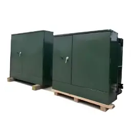
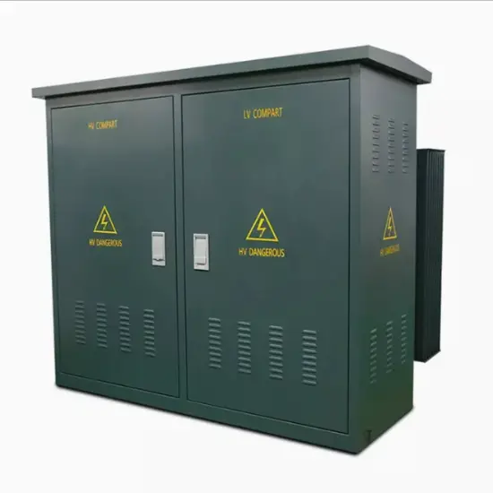
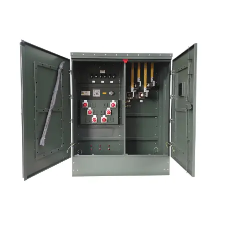
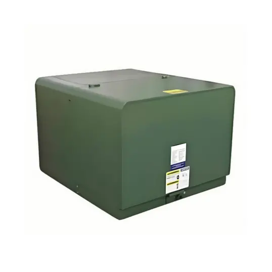
Single-phase pad-mounted transformers are the preferred choice among base-mounted transformers, offering a balance of environmental friendliness, economic efficiency, high efficiency, and safety. These transformers utilize FR3 high-flash-point insulating fluid, providing excellent fire protection performance. Compared with traditional mineral oil transformers, their expected service life is significantly extended. The rated power of these transformers ranges from 10 to 167 kVA, and they are available in various designs such as ANSI Type 1, ANSI Type 2, and Ranch Runner, making them suitable for different application scenarios.

Features:

  • The FR3 fluid is not only biodegradable and non-toxic, but also capable of delivering sustainable performance at an affordable cost. This fluid strictly complies with the ASTM D6871-03 standard and meets the requirements of the IEEE PC57.147 standard which is under application.

  • The product performance fully meets or even exceeds multiple industry standards, covering ANSI (excluding the Ranch Runner front panel), NEMA, and DOE energy efficiency standards.

  • The core and coils are meticulously designed to achieve high reliability and significantly reduce the on-site failure rate. It offers two material options: grain-oriented steel and amorphous steel.

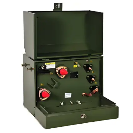
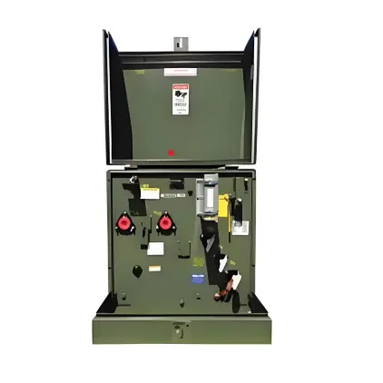
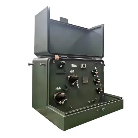
  • The overcurrent protection is well-configured, with Bay-O-Net fuses as standard, and optional current-limiting fuses or weak link components can be selected according to needs.

  • Both high-voltage and low-voltage bushing terminals are tinned, which can accommodate aluminum or copper conductors to ensure stable and efficient electrical connections.

Technical Parameters:

Specifications:

  • Meet or exceeds ANSI, NEMA and DOE2016 standards

  • IEEE standards C57.12.00, C57.12.38, C57.12.28, C57.12.35, C57.12.90, C57. 91 and C57.154

  • NEMA standards, NEMA TR 1 (R2000)

  • Department of Energy Efficiency Standard, 10 CFR Part 431

  • Tank coating exceeds IEEE Std C57.12.28-2005 and C57.12.29-2005 standards (stainless steel units only)

  • Full compliance with IEEE Std C57.12.28-2005 standard enclosure integrity requirements

  • FR3 fluid

  • Cores and coils designed for high reliability and low field failure rates: Available in grain-oriented electrical or amorphous steel

  • The transformer shall be designed in accordance with this specification and shall have an Average Winding Rise (AWR) of one of the following:

  • 55 °C, 55/65 °C, 65 °C

  • The applicable AWR rating shall be specified on the inquiry

  • The transformer shall be designed in accordance with this specification and shall have one of the following kVA ratings:

  • 10, 15, 25, 37.5, 50, 75, 100, 167

  • The applicable kVA rating shall be specified on the inquiry

  • Quality System ISO 9001 certified

Know your supplier
Online store
On-time delivery rate
Response time
100.0%
≤4h
Company overview
Workplace: 10000m² Total staff: Highest Annual Export(usD): 150000000
Workplace: 10000m²
Total staff:
Highest Annual Export(usD): 150000000
Services
Business Type: Design/Manufacture/Sales
Main Categories: High Voltage Electrical Apparatus/Electric transformer
Whole life care manager
Whole-life care management services for equipment procurement, use, maintenance, and after-sales, ensuring safe operation of electrical equipment, continuous control, and worry-free electricity consumption.
The equipment supplier has passed platform qualification certification and technical evaluation, ensuring compliance, professionalism, and reliability from the source.

Related Products

Related Knowledges

  • Impact of DC Bias in Transformers at Renewable Energy Stations Near UHVDC Grounding Electrodes
    Impact of DC Bias in Transformers at Renewable Energy Stations Near UHVDC Grounding ElectrodesWhen the grounding electrode of an Ultra-High-Voltage Direct Current (UHVDC) transmission system is located close to a renewable energy power station, the return current flowing through the earth can cause a rise in ground potential around the electrode area. This ground potential rise leads to a shift in the neutral-point potential of nearby power transformers, inducing DC bias (or DC offset) in their
    01/15/2026
  • HECI GCB for Generators – Fast SF6 Circuit Breaker
    1.Definition and Function1.1 Role of the Generator Circuit BreakerThe Generator Circuit Breaker (GCB) is a controllable disconnect point located between the generator and the step-up transformer, serving as an interface between the generator and the power grid. Its primary functions include isolating generator-side faults and enabling operational control during generator synchronization and grid connection. The operating principle of a GCB is not significantly different from that of a standard c
    01/06/2026
  • Distribution Equipment Transformer Testing, Inspection, and Maintenance
    1.Transformer Maintenance and Inspection Open the low-voltage (LV) circuit breaker of the transformer under maintenance, remove the control power fuse, and hang a “Do Not Close” warning sign on the switch handle. Open the high-voltage (HV) circuit breaker of the transformer under maintenance, close the grounding switch, fully discharge the transformer, lock the HV switchgear, and hang a “Do Not Close” warning sign on the switch handle. For dry-type transformer maintenance: first clean the porcel
    12/25/2025
  • How to Test Insulation Resistance of Distribution Transformers
    In practical work, insulation resistance of distribution transformers is generally measured twice: the insulation resistance between thehigh-voltage (HV) windingand thelow-voltage (LV) winding plus the transformer tank, and the insulation resistance between theLV windingand theHV winding plus the transformer tank.If both measurements yield acceptable values, it indicates that the insulation among the HV winding, LV winding, and transformer tank is qualified. If either measurement fails, pairwise
    12/25/2025
  • Design Principles for Pole-Mounted Distribution Transformers
    Design Principles for Pole-Mounted Distribution Transformers(1) Location and Layout PrinciplesPole-mounted transformer platforms should be located near the load center or close to critical loads, following the principle of “small capacity, multiple locations” to facilitate equipment replacement and maintenance. For residential power supply, three-phase transformers may be installed nearby based on current demand and future growth projections.(2) Capacity Selection for Three-Phase Pole-Mounted Tr
    12/25/2025
  • Transformer Noise Control Solutions for Different Installations
    1.Noise Mitigation for Ground-Level Independent Transformer RoomsMitigation Strategy:First, conduct a power-off inspection and maintenance of the transformer, including replacing aged insulating oil, checking and tightening all fasteners, and cleaning dust from the unit.Second, reinforce the transformer foundation or install vibration isolation devices—such as rubber pads or spring isolators—selected based on the severity of vibration.Finally, strengthen sound insulation at weak points of the ro
    12/25/2025

Related Solutions

  • Choosing Vizman Distribution Transformers: Innovative Customization to Meet Diverse Power Needs
    Distribution transformers are the heart of local electricity distribution systems. They step down voltage, enabling safe and efficient power supply to homes and businesses.At Vizman Electric Power Technology Co., Ltd., we understand the critical role of distribution transformers in the energy ecosystem. That's why we specialize in manufacturing high-quality distribution transformers, providing tailored solutions to meet diverse energy needs.1.Solutions Offered by Vizman Electric Power Technology
    04/16/2025
  • SF6 Circuit Breaker Solutions in High-Voltage Power Systems: A Case Study of VZIMAN Company
    ​1. Challenges in High-Voltage Power Systems​1.1 High-voltage power systems, as the core of power transmission, face critical challenges:​Equipment Performance Limits: With increasing voltage levels (e.g., 500kV and above), traditional circuit breakers struggle to meet high breaking capacities (over 40kA) and rapid insulation recovery requirements.​Overvoltage Risks: Switching capacitive loads (e.g., capacitor banks) may cause reignition, leading to dangerous overvoltages.​Poor Environmental Ada
    05/13/2025
  • VZIMAN Company SF6 Circuit Breaker Solutions for Renewable Energy Grid Integration
    1. Current Challenges in Renewable Energy Grid Integration1.1 ​Grid Frequency Fluctuations and Stability Issues​The intermittency and variability of renewable energy sources (e.g., wind and solar) lead to frequent grid frequency changes. Traditional circuit breakers struggle to respond rapidly to such dynamic loads, potentially causing equipment damage or regional blackouts. For instance, during sudden drops in wind power or abrupt solar output fluctuations, the grid must isolate faults within m
    05/13/2025
Related Free tools
Haven't found the right supplier yet? Let matching verified suppliers find you. Get Quotation Now
Haven't found the right supplier yet? Let matching verified suppliers find you.
Get Quotation Now
Send inquiry
Download
Get the IEE Business Application
Use the IEE-Business app to find equipment, obtain solutions, connect with experts, and participate in industry collaboration anytime, anywhere—fully supporting the development of your power projects and business.