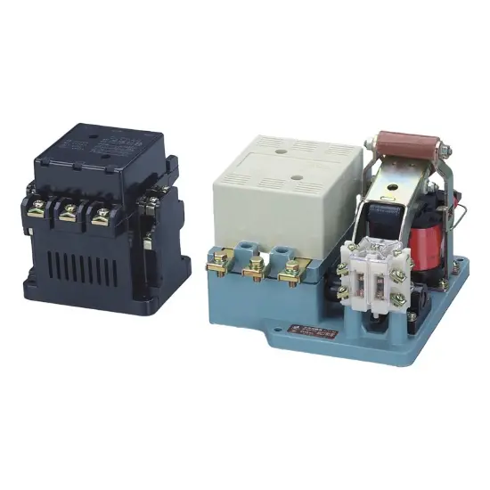
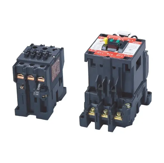
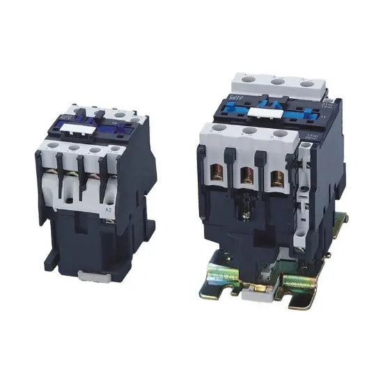
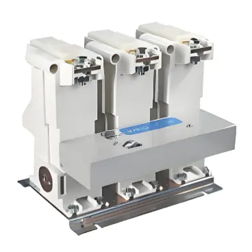
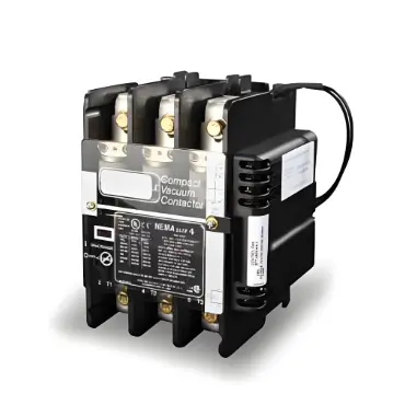
CJX1 Series AC Contactor to protect the circuit

Key attributes
| Brand | Switchgear parts |
| Model NO. | CJX1 Series AC Contactor |
| Rated normal current | 32A |
| Rated frequency | 50/60Hz |
| Series | CJX1 |
Product descriptions from the supplier
Application
CJX1 series AC contactor is suitable for the circuitof AC 50Hz (or 60Hz) and rated working voltage upto 1000V or the circuit of rated working voltage 380Vand rated working current 475A under AC-3 utilization,it is mainly used to make and break circuits in a fardistance or frequently start and control AC motors,it also can be formed into an electromagnetic starterwith suitable thermal overload relay to protect thecircuit against possible overload.
The products are in conformity with such standardsas GB14048.4 and IEC60947-4-1.
Main Techincal Data
Type |
CJX1-9 |
CJX1-12 |
CJX1-16 |
CJX1-22 |
CJX1-32 |
CJX1-38 |
CJX1-45 |
CJX1-63 |
CJX1-75 |
CJX1-85 |
CJX1-110 |
CJX1-140 |
CJX1-170 |
CJX1-205 |
CJX1-250 |
CJX1-300 |
CJX1-400 |
CJX1-475 |
Rated insulation Voltage |
690 |
690 |
690 |
690 |
690 |
690 |
690 |
690 |
690 |
690 |
690 |
690 |
690 |
690 |
690 |
1000 |
1000 |
1000 |
Frequency (Hz) |
50 (or 60) |
50 (or 60) |
50 (or 60) |
50 (or 60) |
50 (or 60) |
50 (or 60) |
50 (or 60) |
50 (or 60) |
50 (or 60) |
50 (or 60) |
50 (or 60) |
50 (or 60) |
50 (or 60) |
50 (or 60) |
50 (or 60) |
50 (or 60) |
50 (or 60) |
50 (or 60) |
Rated Working current - AC-3 380V |
9 |
12 |
16 |
22 |
32 |
38 |
45 |
63 |
75 |
85 |
110 |
140 |
170 |
205 |
250 |
300 |
400 |
475 |
Rated Working current - AC-4 380V |
3.3 |
4.3 |
7.7 |
8.5 |
15.6 |
18.5 |
24 |
28 |
34 |
42 |
54 |
68 |
75 |
96 |
110 |
125 |
150 |
165 |
Max power of controllable motor under AC-3 utilization kW - 220V |
2.2 |
3 |
4 |
5.5 |
8.5 |
11 |
15 |
18.5 |
22 |
28 |
37 |
43 |
55 |
64 |
78 |
93 |
125 |
148 |
Max power of controllable motor under AC-3 utilization kW - 380V |
4 |
5.5 |
7.5 |
11 |
15 |
18.5 |
22 |
30 |
37 |
45 |
55 |
75 |
90 |
110 |
132 |
160 |
200 |
252 |
Max power of controllable motor under AC-3 utilization kW - 660V |
5.5 |
7.2 |
11 |
11 |
23 |
23 |
39 |
55 |
67 |
67 |
100 |
100 |
156 |
156 |
235 |
235 |
375 |
342 |
Conventional thermal current |
20 |
20 |
30 |
30 |
55 |
55 |
90 |
80 |
100 |
100 |
160 |
160 |
210 |
220 |
300 |
300 |
400 |
550 |
Operating frequency - AC-3 |
1200 |
1200 |
1200 |
1200 |
600 |
600 |
600 |
600 |
600 |
600 |
600 |
300 |
300 |
300 |
300 |
300 |
300 |
300 |
Operating frequency - AC-4 |
300 |
300 |
300 |
300 |
300 |
300 |
300 |
300 |
300 |
300 |
300 |
200 |
200 |
130 |
200 |
130 |
150 |
150 |
On-load factor - AC-3 |
40% |
40% |
40% |
40% |
40% |
40% |
40% |
40% |
40% |
40% |
40% |
40% |
40% |
40% |
40% |
40% |
40% |
40% |
Combined with fuse |
NT00-16 |
NT00-20 |
NT00-25 |
NT00-32 |
NT00-50 |
NT00-63 |
NT00-63 |
NT00-80 |
NT00-100 |
NT00-125 |
NT00-160 |
NT00-200 |
NT00-250 |
NT00-250 |
NT00-315 |
NT00-400 |
NT00-500 |
NT00-500 |
Combined with thermal overload relay |
JRS2-12.5 |
JRS2-25 |
JRS2-25 |
JRS2-32 |
JRS2-45 |
JRS2-45 |
JRS2-80 |
JRS2-80 |
JRS2-180 |
JRS2-180 |
JRS2-180 |
JRS2-180 |
JRS2-250 |
JRS2-250 |
JRS2-250 |
JRS2-400 |
JRS2-400 |
JRS2-400 |
Working range of pull-in windings - Attracting |
85%Us~110%Us |
85%Us~110%Us |
85%Us~110%Us |
85%Us~110%Us |
85%Us~110%Us |
85%Us~110%Us |
85%Us~110%Us |
85%Us~110%Us |
85%Us~110%Us |
85%Us~110%Us |
85%Us~110%Us |
85%Us~110%Us |
85%Us~110%Us |
85%Us~110%Us |
85%Us~110%Us |
85%Us~110%Us |
85%Us~110%Us |
85%Us~110%Us |
Working range of pull-in windings - to release |
20%Us~75%Us |
20%Us~75%Us |
20%Us~75%Us |
20%Us~75%Us |
20%Us~75%Us |
20%Us~75%Us |
20%Us~75%Us |
20%Us~75%Us |
20%Us~75%Us |
20%Us~75%Us |
20%Us~75%Us |
20%Us~75%Us |
20%Us~75%Us |
20%Us~75%Us |
20%Us~75%Us |
20%Us~75%Us |
20%Us~75%Us |
20%Us~75%Us |
Voltage of pull-in windings |
24、36、48、110、127、220、380 |
24、36、48、110、127、220、380 |
24、36、48、110、127、220、380 |
24、36、48、110、127、220、380 |
24、36、48、110、127、220、380 |
24、36、48、110、127、220、380 |
24、36、48、110、127、220、380 |
24、36、48、110、127、220、380 |
24、36、48、110、127、220、380 |
24、36、48、110、127、220、380 |
24、36、48、110、127、220、380 |
24、36、48、110、127、220、380 |
24、36、48、110、127、220、380 |
24、36、48、110、127、220、380 |
24、36、48、110、127、220、380 |
24、36、48、110、127、220、380 |
24、36、48、110、127、220、380 |
24、36、48、110、127、220、380 |
Conventional thermal current of auxiliary contact |
10 |
10 |
10 |
10 |
10 |
10 |
10 |
10 |
10 |
10 |
10 |
10 |
10 |
10 |
10 |
10 |
10 |
10 |
Electrical life - AC-3 |
100 |
100 |
100 |
100 |
80 |
80 |
80 |
80 |
80 |
80 |
60 |
60 |
60 |
60 |
60 |
60 |
60 |
60 |
Electrical life - AC-4 |
20 |
20 |
20 |
20 |
15 |
15 |
15 |
15 |
15 |
15 |
10 |
10 |
10 |
10 |
10 |
10 |
10 |
10 |
Weight (kg) |
0.43 |
0.49 |
0.7 |
0.7 |
1.43 |
1.43 |
1.43 |
2.21 |
2.21 |
3.42 |
3.42 |
5.5 |
5.5 |
6.8 |
6.8 |
9.2 |
9.2 |
9.2 |
External And Installation Size


Related Products

Related Knowledges
-
 Main Transformer Accidents and Light Gas Operation Issues1. Accident Record (March 19, 2019)At 16:13 on March 19, 2019, the monitoring background reported a light gas action of No. 3 main transformer. In accordance with the Code for Operation of Power Transformers (DL/T572-2010), operation and maintenance (O&M) personnel inspected the on-site condition of No. 3 main transformer.On-site confirmation: The WBH non-electrical protection panel of No. 3 main transformer reported a Phase B light gas action of the transformer body, and the reset was ineff02/05/2026
 -
 Faults and Handling of Single-phase Grounding in 10kV Distribution LinesCharacteristics and Detection Devices for Single-Phase Ground Faults1. Characteristics of Single-Phase Ground FaultsCentral Alarm Signals:The warning bell rings, and the indicator lamp labeled “Ground Fault on [X] kV Bus Section [Y]” illuminates. In systems with a Petersen coil (arc suppression coil) grounding the neutral point, the “Petersen Coil Operated” indicator also lights up.Insulation Monitoring Voltmeter Indications:The voltage of the faulted phase decreases (in01/30/2026
 -
 Neutral point grounding operation mode for 110kV~220kV power grid transformersThe arrangement of neutral point grounding operation modes for 110kV~220kV power grid transformers shall meet the insulation withstand requirements of transformer neutral points, and shall also strive to keep the zero-sequence impedance of substations basically unchanged, while ensuring that the zero-sequence comprehensive impedance at any short-circuit point in the system does not exceed three times the positive-sequence comprehensive impedance.For 220kV and 110kV transformers in new constructi01/29/2026
 -
 Why Do Substations Use Stones, Gravel, Pebbles, and Crushed Rock?Why Do Substations Use Stones, Gravel, Pebbles, and Crushed Rock?In substations, equipment such as power and distribution transformers, transmission lines, voltage transformers, current transformers, and disconnect switches all require grounding. Beyond grounding, we will now explore in depth why gravel and crushed stone are commonly used in substations. Though they appear ordinary, these stones play a critical safety and functional role.In substation grounding design—especially when multiple gr01/29/2026
 -
 Why Must a Transformer Core Be Grounded at Only One Point? Isn't Multi-Point Grounding More Reliable?Why Does the Transformer Core Need to Be Grounded?During operation, the transformer core, along with the metal structures, parts, and components that fix the core and windings, are all situated in a strong electric field. Under the influence of this electric field, they acquire a relatively high potential with respect to ground. If the core is not grounded, a potential difference will exist between the core and the grounded clamping structures and tank, which may lead to intermittent discharge.I01/29/2026
 -
 Understanding Transformer Neutral GroundingI. What is a Neutral Point?In transformers and generators, the neutral point is a specific point in the winding where the absolute voltage between this point and each external terminal is equal. In the diagram below, pointOrepresents the neutral point.II. Why Does the Neutral Point Need Grounding?The electrical connection method between the neutral point and earth in a three-phase AC power system is called theneutral grounding method. This grounding method directly affects:The safety, reliabilit01/29/2026


