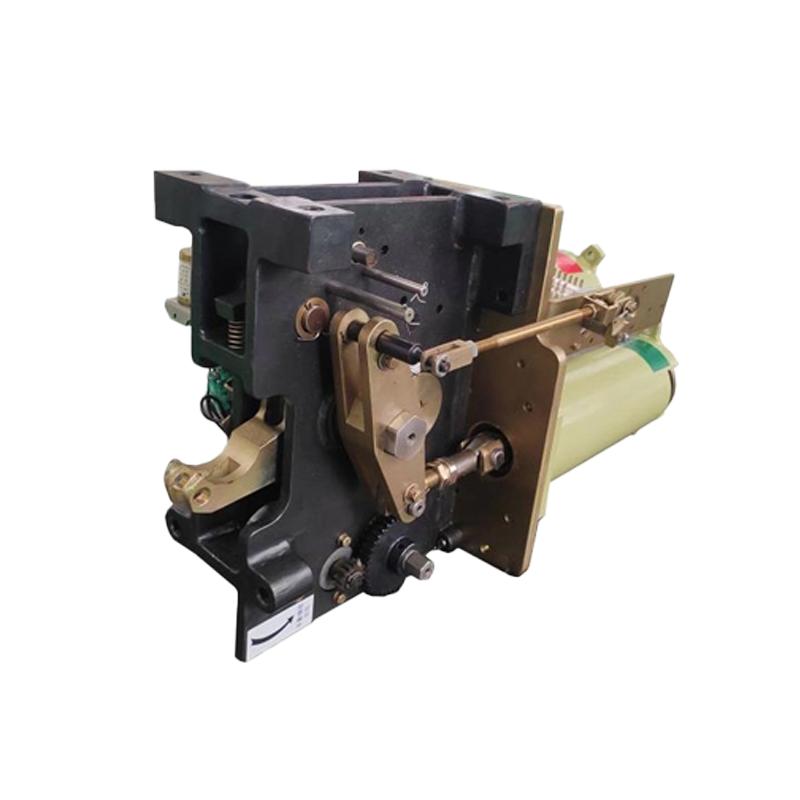
CT40 Spring operated mechanism (dual auxiliary switch)
Key attributes
| Brand | Switchgear parts |
| Model NO. | CT40 Spring operated mechanism (dual auxiliary switch) |
| Rated voltage | 40.5kV |
| Rated frequency | 50/60Hz |
| Series | CT40 |
Product descriptions from the supplier
The CT-40 spring operated mechanism is suitable for operating LW35-40.5 self charging SF6 circuit breakers and switch cabinets with equivalent power to circuit breakers. It can drive the circuit breaker body to perform opening and closing operations, achieving various operations. Using spring energy storage as the power source, coupled with dual auxiliary switches to achieve precise control and status feedback, it is widely used in 10kV-40.5kV medium voltage distribution systems, industrial substations, and distribution networks, providing stable and efficient power support for the opening and closing operations of switchgear and ensuring the safe operation of power systems.
1、 Core working principle: Collaborative control of spring energy storage and dual auxiliary switch
1. Spring energy storage mechanism
The CT40 mechanism uses cylindrical spiral springs as the core energy storage component, and the energy storage process is achieved through manual or electric methods:
Electric energy storage: The motor drives the reduction gear set, which drives the energy storage shaft to rotate and compresses the closing spring through the cam mechanism; When the spring is compressed to the rated stroke, the energy storage pawl and ratchet lock, and the stroke switch triggers the motor to stop, completing the energy storage (energy storage time ≤ 15s). At this time, the mechanism is in a state of waiting to be closed.
Manual energy storage: When the motor fails or there is no power supply, rotate the energy storage shaft manually by shaking the handle, repeat the compression spring and locking process described above, and ensure that the energy storage operation can still be completed in emergency situations.
2. Logic of opening and closing actions
Closing operation: When receiving the closing signal, the closing electromagnet will act, releasing the energy storage pawl, and the closing spring will quickly release energy, pushing the switch device's moving contact to close through the connecting rod transmission mechanism; After the closing is completed, the opening spring is synchronously stretched to store energy, preparing for the opening operation.
Opening operation: When receiving the opening signal, the opening electromagnet (or manual opening handle) will act, the opening lock will release, the opening spring will release energy, and the transmission mechanism will be driven to quickly pull the moving contact to disconnect, cutting off the circuit (opening time ≤ 25ms, ensuring quick disconnection of fault current).
3. The core function of dual auxiliary switches
Different from the single auxiliary switch model, the CT40's dual auxiliary switch design achieves "functional separation and redundancy guarantee", with specific functions including:
State feedback switch: Real time monitoring of the "energy storage status" (stored/not stored) and "closing status" (fully closed/fully opened) of the mechanism, transmitting status signals to the distribution automation system (such as SCADA) for remote monitoring of equipment operation status.
Control interlock switch: Implement logical interlocking of "energy storage closing" and "opening closing", for example: the closing circuit is only connected when the mechanism completes energy storage (triggered by the status feedback switch); When the opening is not in place, the closing operation is locked to prevent equipment damage caused by misoperation and improve operational safety.

Related Products
-
160-250A DNH40 Series Disconnector Switch

-
315-400A DNH40 Series Disconnector Switch

-
3200-4000A DNH40 series isolator switches

-
2000-2500A DNH40 Series Disconnector Switch

-
630-800A DNH40 Series Disconnector Switch

-
HH15 series Disconnector fuse group and disconnector

-
Disconnector Fuse Group HGLR Series, Fuse Switch Disconnector

Related Knowledges
-
 Main Transformer Accidents and Light Gas Operation Issues1. Accident Record (March 19, 2019)At 16:13 on March 19, 2019, the monitoring background reported a light gas action of No. 3 main transformer. In accordance with the Code for Operation of Power Transformers (DL/T572-2010), operation and maintenance (O&M) personnel inspected the on-site condition of No. 3 main transformer.On-site confirmation: The WBH non-electrical protection panel of No. 3 main transformer reported a Phase B light gas action of the transformer body, and the reset was ineff02/05/2026
 -
 Faults and Handling of Single-phase Grounding in 10kV Distribution LinesCharacteristics and Detection Devices for Single-Phase Ground Faults1. Characteristics of Single-Phase Ground FaultsCentral Alarm Signals:The warning bell rings, and the indicator lamp labeled “Ground Fault on [X] kV Bus Section [Y]” illuminates. In systems with a Petersen coil (arc suppression coil) grounding the neutral point, the “Petersen Coil Operated” indicator also lights up.Insulation Monitoring Voltmeter Indications:The voltage of the faulted phase decreases (in01/30/2026
 -
 Neutral point grounding operation mode for 110kV~220kV power grid transformersThe arrangement of neutral point grounding operation modes for 110kV~220kV power grid transformers shall meet the insulation withstand requirements of transformer neutral points, and shall also strive to keep the zero-sequence impedance of substations basically unchanged, while ensuring that the zero-sequence comprehensive impedance at any short-circuit point in the system does not exceed three times the positive-sequence comprehensive impedance.For 220kV and 110kV transformers in new constructi01/29/2026
 -
 Why Do Substations Use Stones, Gravel, Pebbles, and Crushed Rock?Why Do Substations Use Stones, Gravel, Pebbles, and Crushed Rock?In substations, equipment such as power and distribution transformers, transmission lines, voltage transformers, current transformers, and disconnect switches all require grounding. Beyond grounding, we will now explore in depth why gravel and crushed stone are commonly used in substations. Though they appear ordinary, these stones play a critical safety and functional role.In substation grounding design—especially when multiple gr01/29/2026
 -
 Why Must a Transformer Core Be Grounded at Only One Point? Isn't Multi-Point Grounding More Reliable?Why Does the Transformer Core Need to Be Grounded?During operation, the transformer core, along with the metal structures, parts, and components that fix the core and windings, are all situated in a strong electric field. Under the influence of this electric field, they acquire a relatively high potential with respect to ground. If the core is not grounded, a potential difference will exist between the core and the grounded clamping structures and tank, which may lead to intermittent discharge.I01/29/2026
 -
 Understanding Transformer Neutral GroundingI. What is a Neutral Point?In transformers and generators, the neutral point is a specific point in the winding where the absolute voltage between this point and each external terminal is equal. In the diagram below, pointOrepresents the neutral point.II. Why Does the Neutral Point Need Grounding?The electrical connection method between the neutral point and earth in a three-phase AC power system is called theneutral grounding method. This grounding method directly affects:The safety, reliabilit01/29/2026


