• Product
  • Suppliers
  • Manufacturers
  • Solutions
  • Free tools
  • Knowledges
  • Experts
  • Communities
Search


Hollow Wrist Robot

  • Hollow Wrist Robot
  • Hollow Wrist Robot
  • Hollow Wrist Robot

Key attributes

Brand Wone Store
Model NO. Hollow Wrist Robot
Rated Load Capacity 5kg
degree of freedom 6-direction
Maximum working stroke 1555mm
Series JH

Product descriptions from the supplier

Description

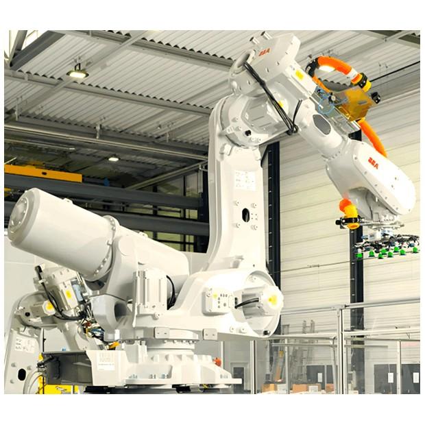
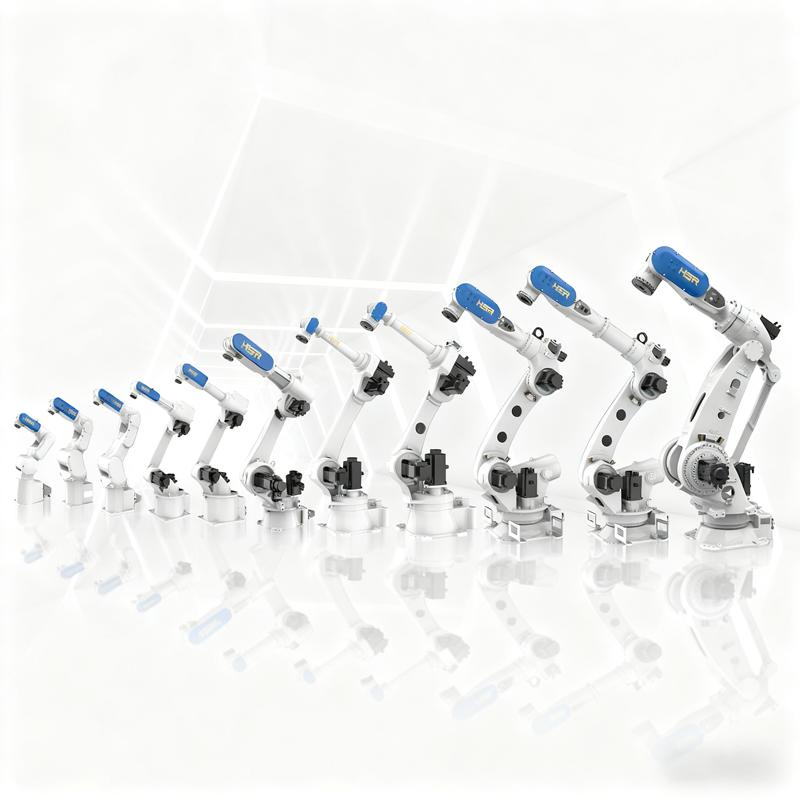
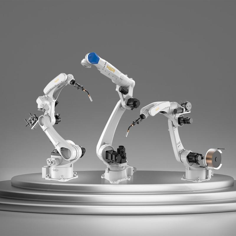
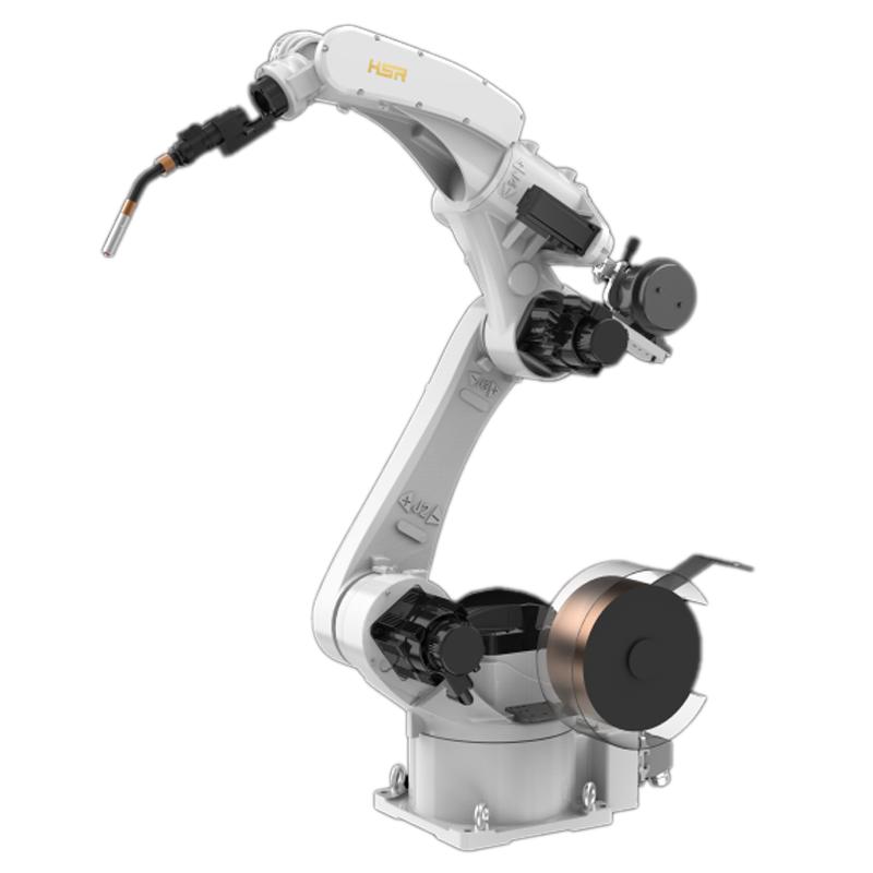
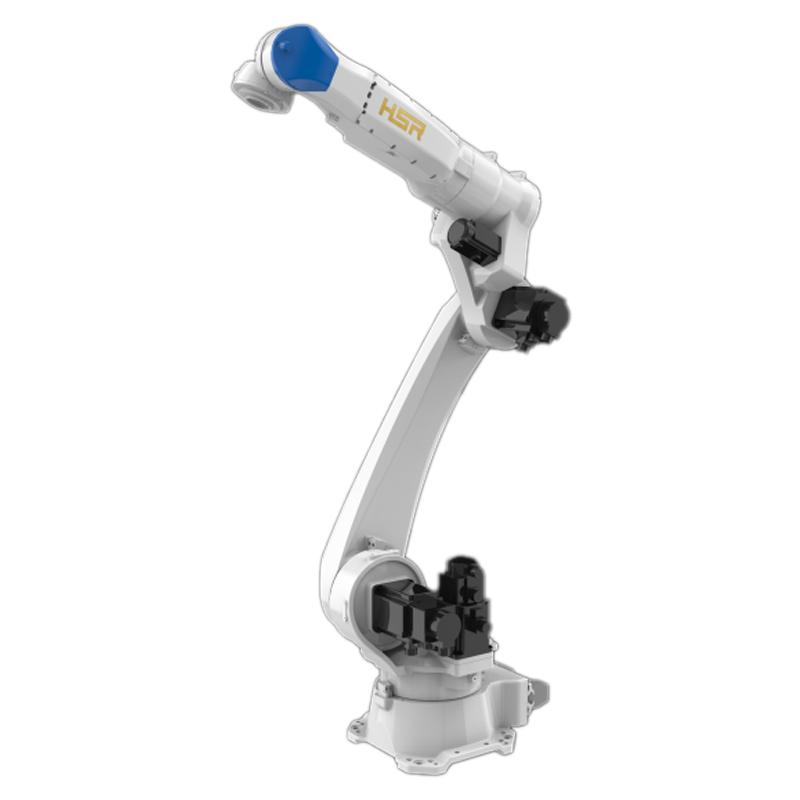
The large hollow wrist robot developed by JH Series Robot is a new breakthrough in product research and development technology for many years. It is superior to regular general-purpose products in terms of ease of use and coverage width of application scenarios, and has the unique advantages of large hollow, high speed and high precision.

Key features:

1. High rigidity: 40% higher rigidity compared to the previous generation, delivering improved stability and outstanding performance in reducing operational vibration.

2. High Speed: By incorporating a higher-speed motor and a superior-performing gearbox, we achieve faster cycle times and enhanced operational efficiency.

3. High Precision: The new-generation welding robot achieves a repeat positioning accuracy of up to ±0.05mm, with trajectory accuracy and repeatability—along with other precision metrics—showing a 20% improvement over the previous generation.

4. Excellent Reach: The working radius reaches up to 2000 mm, with each axis offering a significantly improved range of motion compared to the previous generation—resulting in overall enhanced accessibility.

5. Practicality: With a smaller wrist size, it significantly enhances the convenience of teaching demonstrations. The hollow structure allows for the use of a hollow welding torch.

6. Strong Anti-Interference Capability: The robot features a completely new anti-interference structure, significantly enhancing its ability to withstand external disturbances.

Technology Parameters

Industrial robots JH605-1500 JH615-2000 JH620-1800
Degrees of freedom 6 6 6
Maximum load 5kg 15kg 20kg
Maximum working radius 1494mm 2000mm 1800mm
Repeat positioning accuracy ±0.05 m ±0.05 mm ±0.05 mm
Range of motion J1 ±170° ±165° ±165°
J2 -175°/+60° -165°/+75° -165°/+75°
J3 +6° / +270° -15°/ +260° -15°/ +260°
J4 ±180° ±170° ±170°
J5 -120° / +150° ±140° ±140°
J6 ±360° ±400° ±400°
Maximum speed J1 225°/s, 3.92 rad/s 220°/s, 3.84 rad/s 220°/s, 3.84 rad/s
J2 225°/s, 3.92 rad/s 205°/s, 3.58 rad/s 205°/s, 3.58 rad/s
J3 252°/s, 4.40 rad/s 220°/s, 3.84 rad/s 220°/s, 3.84 rad/s
J4 407°/s, 7.10 rad/s 330°/s, 5.76 rad/s 330°/s, 5.76 rad/s
J5 600°/s, 10.47 rad/s 420°/s, 7.33 rad/s 420°/s, 7.33 rad/s
J6 927°/s, 16.18 rad/s 670°/s, 11.7 rad/s 670°/s, 11.7 rad/s
Allowing the moment of inertia J6 0.2 kgm3 2.8 kgm3 2.8 kgm3
J5 0.4 kgm3 2.2 kgm3 2.2 kgm3
J4 0.4 kgm3 1 kgm3 1 kgm3
Allowable Torque J6 6.5Nm 60Nm 60Nm
J5 12Nm 52Nm 52Nm
J4 12Nm 32Nm 32Nm
Applicable Environment Temperature 0°C to 45°C 0°C to 45°C 0°C to 45°C
Humidity 20% to 80% 20% to 80% 20% to 80%
Other Avoid contact with flammable, explosive, or corrosive gases and liquids, and keep away from sources of electronic noise (such as plasma). Avoid contact with flammable, explosive, or corrosive gases and liquids, and keep away from sources of electronic noise (such as plasma). Avoid contact with flammable, explosive, or corrosive gases and liquids, and keep away from sources of electronic noise (such as plasma).
Teaching device cable length 8m 8m 8m
Body-to-cabinet connection cable length 5m 5m 5m
I/O parameters Digital inputs: 32-bit (NPN), 32-bit outputs (NPN) Digital quantities: 32-bit input, 31-bit output Digital quantities: 32-bit input, 31-bit output
Body-prepared signal cable 24-bit, 4-bit (wiring method for aviation connector: soldering) 24-bit 24-bit
Reserved air circuit 1xφ8 3xφ8 3xφ8
Power capacity 4.5kVA 6.9kVA 6.9kVA
Rated Power 3.6kW 5kW 5kW
Rated Voltage Single-phase AC 220V Three-phase 380V Three-phase 380V
Rated current 19A 9.3A 9.3A
Intrusion Protection Rating IP54 IP54 (arm IP67) IP54 (arm IP67)
Installation method Ground, inverted, and side-mounted installations Ground, inverted, and side-mounted installations Ground, inverted, and side-mounted installations
Body weight 185kg 285kg 280kg
Protection rating of control cabinets IP20 IP54 IP54
Control cabinet weight 15kg 28kg 28kg


Know your supplier
Online store
On-time delivery rate
Response time
100.0%
≤4h
Company overview
Workplace: 1000m² Total staff: Highest Annual Export(usD): 300000000
Workplace: 1000m²
Total staff:
Highest Annual Export(usD): 300000000
Services
Business Type: Sales
Main Categories: Wire cable/High Voltage Electrical Apparatus/Low Voltage Electrical Apparatus/Instrument meters/New energy/Tester/Integrated Electrical Equipment/Production equipment/Generator/Electrical fittings/Instrument Transformer/Equipment Parts
Whole life care manager
Whole-life care management services for equipment procurement, use, maintenance, and after-sales, ensuring safe operation of electrical equipment, continuous control, and worry-free electricity consumption.
The equipment supplier has passed platform qualification certification and technical evaluation, ensuring compliance, professionalism, and reliability from the source.

Related Products

Related Knowledges

  • Faults and Handling of Single-phase Grounding in 10kV Distribution Lines
    Characteristics and Detection Devices for Single-Phase Ground Faults1. Characteristics of Single-Phase Ground FaultsCentral Alarm Signals:The warning bell rings, and the indicator lamp labeled “Ground Fault on [X] kV Bus Section [Y]” illuminates. In systems with a Petersen coil (arc suppression coil) grounding the neutral point, the “Petersen Coil Operated” indicator also lights up.Insulation Monitoring Voltmeter Indications:The voltage of the faulted phase decreases (in
    01/30/2026
  • Neutral point grounding operation mode for 110kV~220kV power grid transformers
    The arrangement of neutral point grounding operation modes for 110kV~220kV power grid transformers shall meet the insulation withstand requirements of transformer neutral points, and shall also strive to keep the zero-sequence impedance of substations basically unchanged, while ensuring that the zero-sequence comprehensive impedance at any short-circuit point in the system does not exceed three times the positive-sequence comprehensive impedance.For 220kV and 110kV transformers in new constructi
    01/29/2026
  • Why Do Substations Use Stones, Gravel, Pebbles, and Crushed Rock?
    Why Do Substations Use Stones, Gravel, Pebbles, and Crushed Rock?In substations, equipment such as power and distribution transformers, transmission lines, voltage transformers, current transformers, and disconnect switches all require grounding. Beyond grounding, we will now explore in depth why gravel and crushed stone are commonly used in substations. Though they appear ordinary, these stones play a critical safety and functional role.In substation grounding design—especially when multiple gr
    01/29/2026
  • Why Must a Transformer Core Be Grounded at Only One Point? Isn't Multi-Point Grounding More Reliable?
    Why Does the Transformer Core Need to Be Grounded?During operation, the transformer core, along with the metal structures, parts, and components that fix the core and windings, are all situated in a strong electric field. Under the influence of this electric field, they acquire a relatively high potential with respect to ground. If the core is not grounded, a potential difference will exist between the core and the grounded clamping structures and tank, which may lead to intermittent discharge.I
    01/29/2026
  • Understanding Transformer Neutral Grounding
    I. What is a Neutral Point?In transformers and generators, the neutral point is a specific point in the winding where the absolute voltage between this point and each external terminal is equal. In the diagram below, pointOrepresents the neutral point.II. Why Does the Neutral Point Need Grounding?The electrical connection method between the neutral point and earth in a three-phase AC power system is called theneutral grounding method. This grounding method directly affects:The safety, reliabilit
    01/29/2026
  • What’s the Difference Between Rectifier Transformers and Power Transformers?
    What is a Rectifier Transformer?"Power conversion" is a general term encompassing rectification, inversion, and frequency conversion, with rectification being the most widely used among them. Rectifier equipment converts input AC power into DC output through rectification and filtering. A rectifier transformer serves as the power supply transformer for such rectifier equipment. In industrial applications, most DC power supplies are obtained by combining a rectifier transformer with rectifier equ
    01/29/2026

Related Solutions

  • Dedicated Vacuum Contactor Solution for Port Shore Power Systems
    I. Background and Challenges​Shore power systems have become core technical equipment for ports to reduce carbon emissions and noise pollution. However, these systems face two major challenges in the harsh operational environment of ports:​Severe Environmental Corrosion: High humidity and salt spray in port areas cause serious corrosion to metal components and enclosures of electrical equipment, significantly impacting electrical lifespan and operational reliability.​High Switching Requirements:
    09/13/2025
  • ABB Vacuum Contactor KC2 Power Supply System Technical Transformation Plan
    Issue Overview​The 10kV air compressor starting system of a company utilizes the ABB vacuum contactor KC2 as the control component for the operating circuit. The dedicated wide-voltage power supply module paired with this contactor presents the following issues:​Frequent failures: The power supply module fails to properly transition the voltage from 300V to 12V, resulting in fuse blowouts.​Poor heat dissipation: Enclosed installation of the module leads to insufficient heat dissipation, acceler
    09/13/2025
  • Solution for Medium-Voltage Motor Control and Protection Using Vacuum Contactor-Fuse (VCF) in a Coal Conveying System
    1.Project BackgroundA coal conveying system comprises 15 belt conveyors driven by medium-voltage motors. The system operates under complex conditions, with motors often subjected to heavy loads and frequent starts. To address these challenges and achieve effective control and reliable protection during motor startup, the project comprehensively adopts Vacuum Contactor-Fuse (VCF) combination devices for the 6kV medium-voltage motor power distribution. This solution details the technical features,
    09/13/2025
Haven't found the right supplier yet? Let matching verified suppliers find you. Get Quotation Now
Haven't found the right supplier yet? Let matching verified suppliers find you.
Get Quotation Now
Send inquiry
+86
Click to upload file
Download
Get the IEE Business Application
Use the IEE-Business app to find equipment, obtain solutions, connect with experts, and participate in industry collaboration anytime, anywhere—fully supporting the development of your power projects and business.