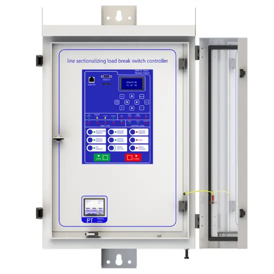
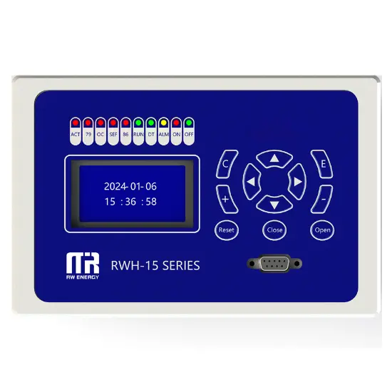
Line Sectionalizing Load Break Switch Controller
Key attributes
| Brand | RW Energy |
| Model NO. | Line Sectionalizing Load Break Switch Controller |
| Rated voltage | 230V ±20% |
| Rated frequency | 50/60Hz |
| Electric energy consumption | ≤5W |
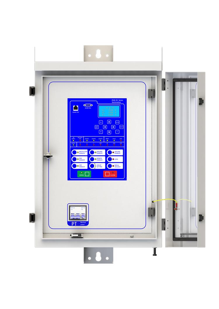
| Series | RWK-38 |
Product descriptions from the supplier
Description
RWK-381 line sectionalizing load break switch controller is a kind of switch which must cooperate with superior switch. It can’t cut off the fault current, it only trip when the line is low-voltage or no-current.
RWK-381 line sectionalizing load break switch controller adopts IT operation mode. When a fault happed, the controller will record the fault times. If the times come to the setting value, the controller will trip after the line is low-voltage or no-current.
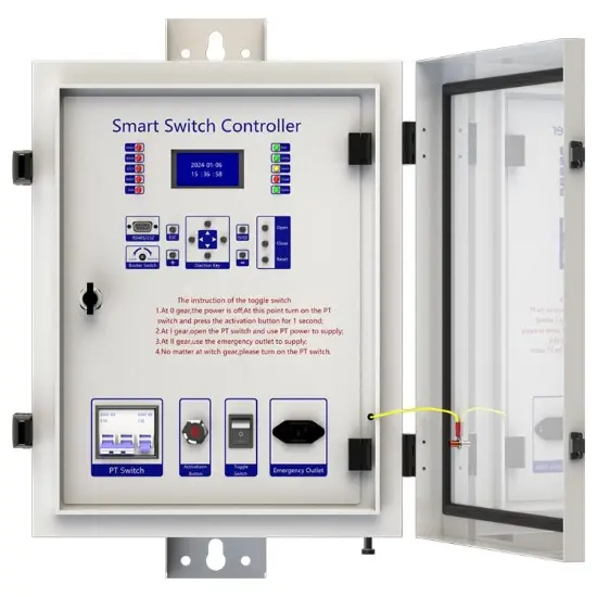
The controlling box is made of stainless steel, the surface is dealt with painting, anticorrosion, can be used in outdoor environments.
It has charging circuit: It could take AC220V charging power supply from outside. If there is no power supply outside, it also could achieve opening/closing operation and all controller functions with battery. Besides that, it is set with anti-over discharge circuit for protecting the battery when there is no electricity of the power supply outside for a long time.
Main function introduction
1. Protection relay functions:
1) Section function,
2) 50 Instantaneous/Definite-Time Overcurrent (P.OC),
3) 51 Phase Time-Overcurrent (P.OC2/P.OC3),
4) 49 Overload
5) 50N Residual Ground Instantaneous/Definite-Time Overcurrent(G.OC),
6) 51N Residual Ground Instantaneous/Definite-Time Overcurrent (G.OC2 /G. OC3) ,
7) 50SEF Sensitive Earth Fault (SEF),
8) 51C Cold Load,
9) TRSOTF Switch-Onto-Fault (SOTF)
10) 27 Under Voltage (L.Under volt) ,
11) 59 Over Voltage (L.Over volt),
2. Supervision functions:
1) 74T/CCS Trip & Close Circuit Supervision,
2) 60VTS VT Supervision .
3. Control functions:
1) 60VTS Lockout ,
2) circuit-breaker control.
4. Monitoring Functions:
1) Primary/Secondary Phases and Earth Currents,
2) Direction,
3) Primary/Secondary Line and Phase Voltages,
4) Apparent Power and Power Factor,
5) Real and Reactive Power,
6) Positive Phase Sequence Voltage,
7) Negative Phase Sequence Voltage & Current,
8) Zero Phase Sequence Voltage,
9) Earth Current With 3RD Harmonics,
10) Frequency,
11) Binary Input/Output status,
12) Trip circuit healthy/failure,
13) Time and date,
14) Event records
15) Counters,
16) Wear.
5. Communication functions:
a. Communication interface: RS485X1,RJ45X1
b. Communication protocol: IEC60870-5-101; IEC60870-5-104; DNP3.0; Modbus-RTU
c. PC software: RWK381HB-V2.1.3,The address of the information body can be edited and queried by PC software,
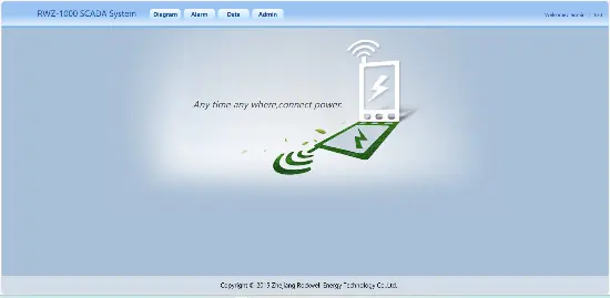
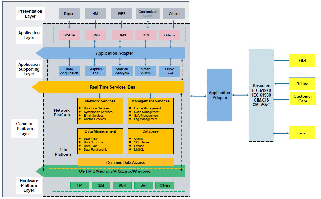
d. SCADA system: SCADA systems that support the four protocols shown in "b.”.
6. Data Storage functions:
1) Event Records,
2) Fault Records,
3) Measurands.
7. remote signaling remote measuring, remote controlling function can be customized address.
Technology parameters

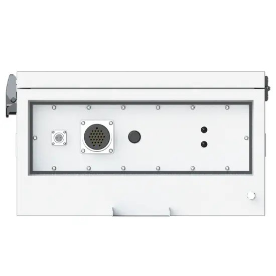
Device structure


About customization
The following optional functions are available: cabinet heating defrosting device, battery upgrade to lithium battery or other storage equipment, GPRS communication module,1~2 signal indicators,1~4 protection pressure plates, the second voltage transformer, custom aviation socket signal definition.
For detailed customization, please contact the salesman.
Q: What is line sectionalizing load break switch?
A:line sectionalizing load break switch is an important device used in power lines. Its main function is to segment the line according to certain rules. The advantage of this is that when a certain segment of the line fails, the segment switch can isolate the faulty segment from the normally functioning line.
Q: How does it determine the segments?
A: The segmentation is usually determined according to the load distribution, geographical layout and power supply reliability requirements of the line. For example, in the area where the load is more concentrated, a separate segment may be divided; Or by geographical area, such as a block or an industrial area.
Q: What is the significance of line sectionalizing load break switch for power system?
A: It can improve the reliability and flexibility of the power system. When a fault occurs, it can quickly isolate the fault, reduce the scope of power outage, so that power maintenance personnel can be more targeted to troubleshoot the fault, and other unaffected segments can continue to supply power normally, ensuring that


This device can connect to SCADA System and DMS, and you can connect the terminal to the server according to your local network conditions. This terminal supports CDMA (3G)/LTE (4G)/ NR(5G), ETH, fiber optic and other ways to access the network. You can also contact us directly, and we will provide you with a solution for distribution network automation.
A: AC SUPPLY: AC POWER ON
BATTERY FAIL: BATTERY DISCHARGED
count1/2/3: Sectionalizer counts once/twice/three times
RESET: Sectionalizer reset
CYCLE: Sectionalizer is in progress
LOCK: Sectionalizer lock
COMMU: Communication is in progress
A/B/C: Phase A/B/C fault
OCR:over current fault
EF: earth fault
OVR/UVR: Over voltage/under voltage
This protective device supports 2-channel serial data communication, which is independent of each other. One channel is RS485, and the other channel is ETH, which can be configured separately. The configuration method is as follows:
- Enter the settings page: Edit → Port → Port1 set;
- Configure communication function on/off: Scroll down and find Comm1 Status set to 1, indicating it is turned on, and 0 indicates it is turned off. The default setting is open;
- Set communication baud rate: According to the baud rate configuration of RTU or protocol converter, the default value is 9600;
- Set communication protocol: There are four protocols to choose from, corresponding to setting 1 as IEC-60870-101, setting 2 as IEC-60870-104, setting 3 as DNP3.0, setting 4 as ModBus RTU, default as IEC-60870-101;
- Set communication balance (only valid for multiple IEC-60870-101): Set 1 to IEC-60870-101 protocol balance mode and 0 to imbalance mode;
- Set the communication source address: Set the value to 1-65535, default value to 1;
- Set the target address for the report: set the value to 0-65535, default value to 1;
- Set active upload: 0 does not actively upload, 1 actively uploads, default value is 1;
- Set remote signaling cycle: set to 1 periodic upload, 0 no upload
- Set the remote signaling cycle time: Set the time in seconds
- Set telemetry cycle: set to 1 periodic upload, 0 no upload
- Set telemetry cycle time: Set the time in seconds
- Save settings: After completing the settings, press the "Enter" key, enter the password 0099 (some models are 0077), press the "Enter" key again, and the screen will prompt "Save successful", indicating that the settings have been saved.
At this point, channel 1 has been established, and channel 2 is established in the same way as channel 1. At the same time, channel 2 also needs to be configured with network ports. The steps are as follows:
Connect to the computer using an Ethernet cable and access 192.168.0.7 via WEB (the computer's IP address must be 192.168.0.XXX network segment, otherwise it cannot be accessed). After entering the background, select the "Local IP Config" button to set the terminal's DHCP mode, static address, subnet mask, and gateway address; Select the "Serial Port" button in the background, set the output port of the communication protocol in "Local Port number", and set the network port working mode (TCP Server/TCP Client) in "Local Port number". When setting TCP Client, fill in the TCP server address below. At this point, all communication settings have been configured
NOTE: 1. The product has been set to default settings before delivery to meet most usage scenarios. It is not recommended to make modifications or only modify controllable items (such as modifying communication protocols, configuring communication functions on/off, etc.) when it can be used normally
Yes, this device has corresponding upper computer software (only available in windows-X86 version), which can be connected to the terminal through a serial port or network port, enabling fixed parameter configuration and viewing, address configuration for remote signaling, telemetry, and control, viewing of event reports, monitoring of electricity meters, packet capture of communication messages, and simulation of remote control functions.

Related Products
-
General Protection Device
-
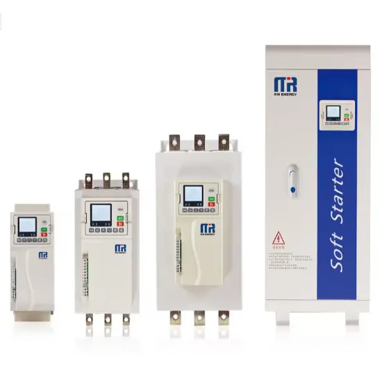
RWS-7000 Built - in bypass type motor soft starter
-
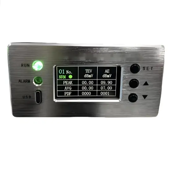
RWJS Partial Discharge Online Monitoring System for Ring Main Units
-
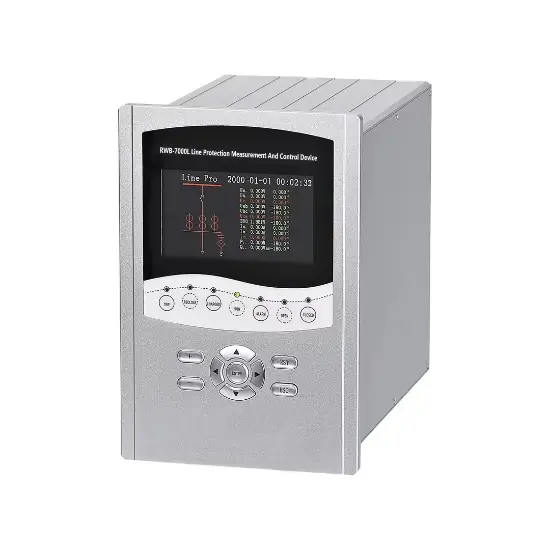
RWB-7000L Line Protection Measurement And Control Device
-
Feeder Terminal Unit
-
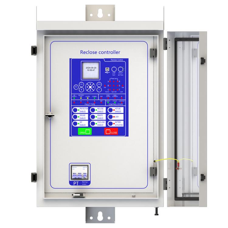
Advanced Recloser Controller

-
On-line Monitoring System for Distribution Lines
Related Knowledges
-
 Faults and Handling of Single-phase Grounding in 10kV Distribution LinesCharacteristics and Detection Devices for Single-Phase Ground Faults1. Characteristics of Single-Phase Ground FaultsCentral Alarm Signals:The warning bell rings, and the indicator lamp labeled “Ground Fault on [X] kV Bus Section [Y]” illuminates. In systems with a Petersen coil (arc suppression coil) grounding the neutral point, the “Petersen Coil Operated” indicator also lights up.Insulation Monitoring Voltmeter Indications:The voltage of the faulted phase decreases (in01/30/2026
 -
 Neutral point grounding operation mode for 110kV~220kV power grid transformersThe arrangement of neutral point grounding operation modes for 110kV~220kV power grid transformers shall meet the insulation withstand requirements of transformer neutral points, and shall also strive to keep the zero-sequence impedance of substations basically unchanged, while ensuring that the zero-sequence comprehensive impedance at any short-circuit point in the system does not exceed three times the positive-sequence comprehensive impedance.For 220kV and 110kV transformers in new constructi01/29/2026
 -
 Why Do Substations Use Stones, Gravel, Pebbles, and Crushed Rock?Why Do Substations Use Stones, Gravel, Pebbles, and Crushed Rock?In substations, equipment such as power and distribution transformers, transmission lines, voltage transformers, current transformers, and disconnect switches all require grounding. Beyond grounding, we will now explore in depth why gravel and crushed stone are commonly used in substations. Though they appear ordinary, these stones play a critical safety and functional role.In substation grounding design—especially when multiple gr01/29/2026
 -
 Why Must a Transformer Core Be Grounded at Only One Point? Isn't Multi-Point Grounding More Reliable?Why Does the Transformer Core Need to Be Grounded?During operation, the transformer core, along with the metal structures, parts, and components that fix the core and windings, are all situated in a strong electric field. Under the influence of this electric field, they acquire a relatively high potential with respect to ground. If the core is not grounded, a potential difference will exist between the core and the grounded clamping structures and tank, which may lead to intermittent discharge.I01/29/2026
 -
 Understanding Transformer Neutral GroundingI. What is a Neutral Point?In transformers and generators, the neutral point is a specific point in the winding where the absolute voltage between this point and each external terminal is equal. In the diagram below, pointOrepresents the neutral point.II. Why Does the Neutral Point Need Grounding?The electrical connection method between the neutral point and earth in a three-phase AC power system is called theneutral grounding method. This grounding method directly affects:The safety, reliabilit01/29/2026
 -
 What’s the Difference Between Rectifier Transformers and Power Transformers?What is a Rectifier Transformer?"Power conversion" is a general term encompassing rectification, inversion, and frequency conversion, with rectification being the most widely used among them. Rectifier equipment converts input AC power into DC output through rectification and filtering. A rectifier transformer serves as the power supply transformer for such rectifier equipment. In industrial applications, most DC power supplies are obtained by combining a rectifier transformer with rectifier equ01/29/2026
Related Solutions
-
 Distribution automation systems solutionsWhat are the difficulties in overhead line operation and maintenance?Difficulty one:Overhead lines of distribution network have wide coverage,complicatedterrain,many radiation branches and distributed power supply,resultingin "many line faults and difficulty in fault troubleshooting".Difficulty Two:Manual troubleshooting is time-consuming and laborious.Meanwhile,therunning current,voltage and switching state of the line cannot be graspedin real time,because of the lack of intelligent technical m04/22/2025
 -
 RW8000 DMS Distribution Management System SolutionsOverviewNowadays, the development trend of power grid is intellectualization. As an important part of power grid, the power distribution system is very close to the customers and it has to run properly. The distribution management system (DMS)played an important role in it.Introduction:RW8000 power distribution management system (DMS) is designed for the smart grids. It is based on real-time application, centered on distribution network operation and management, focusing on the business process09/07/2023
 -
 High-Precision Electrical Parameter Monitoring System Solution1.IntroductionWith the increasingly stringent requirements for power supply quality in high-end facilities such as precision manufacturing, medical diagnosis, and data centers, traditional power monitoring systems, due to their low sampling accuracy and weak data analysis capabilities, can no longer meet the demand for deep insight and precise management of power quality. In response, we are introducing a new generation High-Precision Electrical Parameter Monitoring System. With millisecond-l09/28/2025


