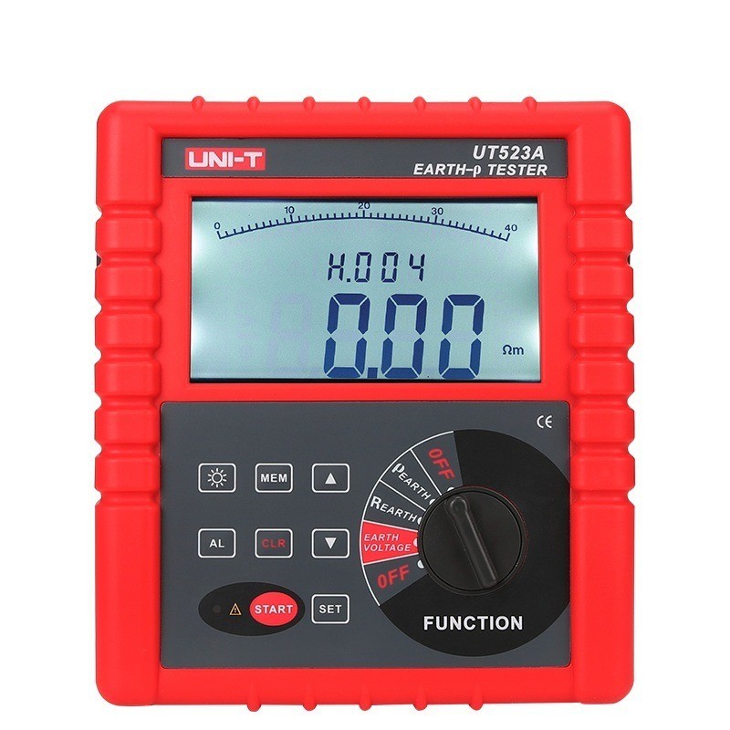
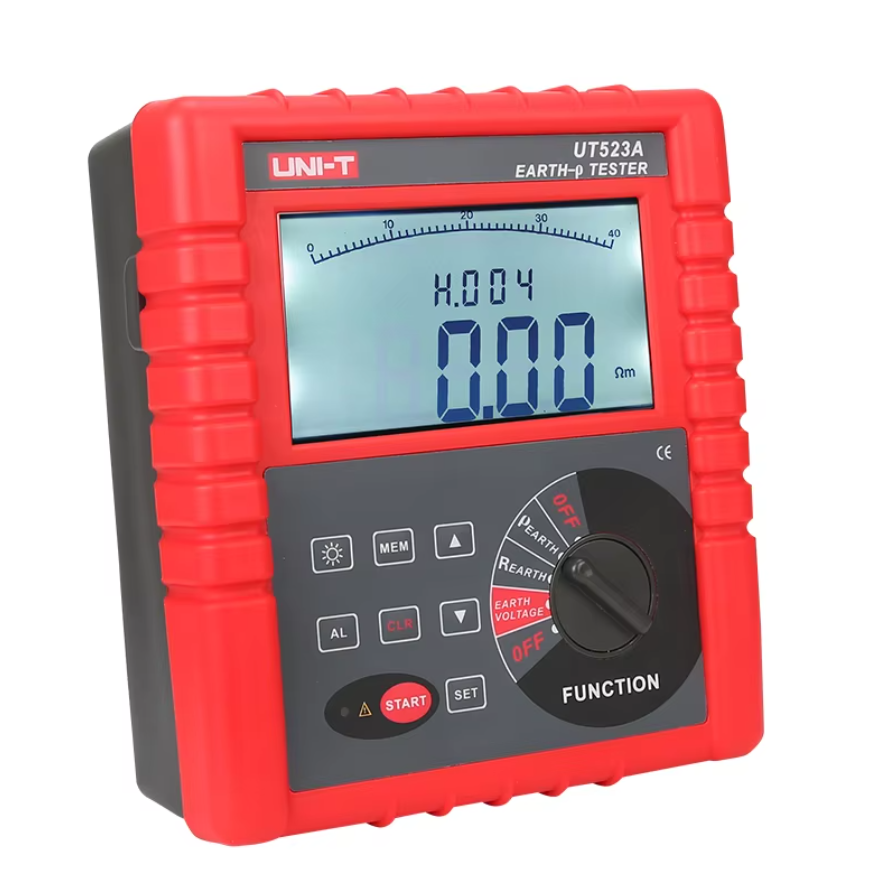
Handheld Resistance Voltage Intelligent Grounding Resistance Tester Multi-Function Test Insulation Resistance Meter

Key attributes
| Brand | Wone Store |
| Model NO. | UT523A Handheld Resistance Voltage Intelligent Grounding Resistance Tester Multi-Function Test Insulation Resistance Meter |
| Earth resistance | 200Ω~1999Ω |
| Soil resistivity | 99.99kΩm |
| Earth voltage | AC 0.00~750V |
| Series | GRM |
Product descriptions from the supplier
Description
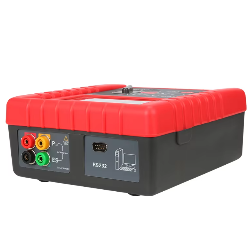
UT523A intelligent grounding resistance tester is specially designed and manufactured for on-site measurement of grounding resistance, soil resistivity, grounding voltage and AC voltage. It adopts the latest digital and micro-processing technology, precise 4-wire method, 3-wire method and simple 2-wire method.
Feature
Precise 4-wire method, 3-wire method and simple 2-wire method to measure ground resistance,
ground resistance
Soil resistivity
ground voltage
AC voltage measurement
Specifications


How is ground resistance measured?

Online store
On-time delivery rate
Response time
100.0%
≤4h
Company overview
Workplace: 1000m²
Total staff:
Highest Annual Export(usD): 300000000
Services
Business Type: Sales
Main Categories: Wire cable/High Voltage Electrical Apparatus/Low Voltage Electrical Apparatus/Instrument meters/New energy/Tester/Integrated Electrical Equipment/Production equipment/Generator/Electrical fittings/Instrument Transformer/Equipment Parts
Whole life care manager
Whole-life care management services for equipment procurement, use, maintenance, and after-sales, ensuring safe operation of electrical equipment, continuous control, and worry-free electricity consumption.
The equipment supplier has passed platform qualification certification and technical evaluation, ensuring compliance, professionalism, and reliability from the source.
Related Products
-
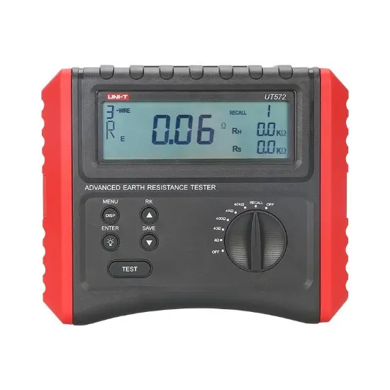
Advance Earth Resistance Tester Digital Ground Resistance Test/Soil Resistivity Test Data Storage LCD Backlight
-
NF-822 High Voltage Underground Wire Detector Underground Wire Tracker

-
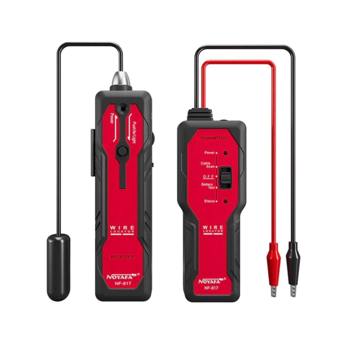
NF-817 Underground Wire Locator
-
Wire Tracer for Underground and Wall Electrical Wires and Pipes

-
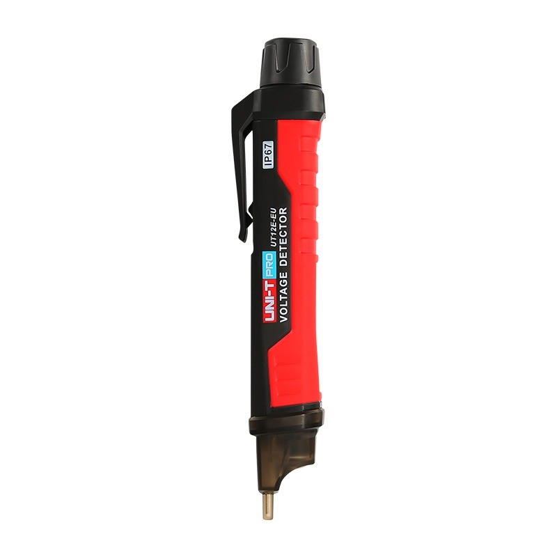
AC voltage detector pen Tester with vibration mode HLX
-
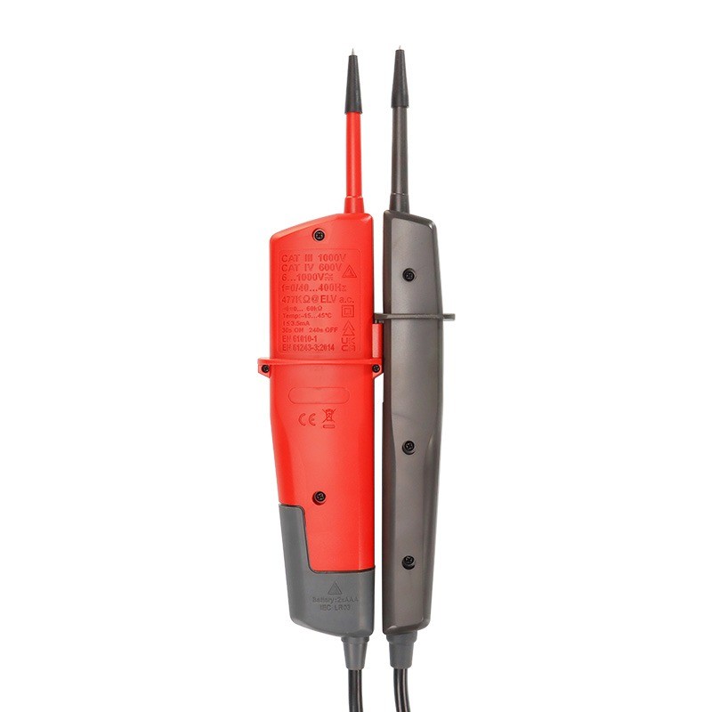
Pocket Voltage And Continuity Testers 12V-690V LED AC/DC Voltage Indication Auto Range Voltmeter Voltage Tester
-
400V, 690V, 1000V (AC/DC) Voltage and Continuity Tester

Related Knowledges
-
 Faults and Handling of Single-phase Grounding in 10kV Distribution LinesCharacteristics and Detection Devices for Single-Phase Ground Faults1. Characteristics of Single-Phase Ground FaultsCentral Alarm Signals:The warning bell rings, and the indicator lamp labeled “Ground Fault on [X] kV Bus Section [Y]” illuminates. In systems with a Petersen coil (arc suppression coil) grounding the neutral point, the “Petersen Coil Operated” indicator also lights up.Insulation Monitoring Voltmeter Indications:The voltage of the faulted phase decreases (in01/30/2026
 -
 Neutral point grounding operation mode for 110kV~220kV power grid transformersThe arrangement of neutral point grounding operation modes for 110kV~220kV power grid transformers shall meet the insulation withstand requirements of transformer neutral points, and shall also strive to keep the zero-sequence impedance of substations basically unchanged, while ensuring that the zero-sequence comprehensive impedance at any short-circuit point in the system does not exceed three times the positive-sequence comprehensive impedance.For 220kV and 110kV transformers in new constructi01/29/2026
 -
 Why Do Substations Use Stones, Gravel, Pebbles, and Crushed Rock?Why Do Substations Use Stones, Gravel, Pebbles, and Crushed Rock?In substations, equipment such as power and distribution transformers, transmission lines, voltage transformers, current transformers, and disconnect switches all require grounding. Beyond grounding, we will now explore in depth why gravel and crushed stone are commonly used in substations. Though they appear ordinary, these stones play a critical safety and functional role.In substation grounding design—especially when multiple gr01/29/2026
 -
 Why Must a Transformer Core Be Grounded at Only One Point? Isn't Multi-Point Grounding More Reliable?Why Does the Transformer Core Need to Be Grounded?During operation, the transformer core, along with the metal structures, parts, and components that fix the core and windings, are all situated in a strong electric field. Under the influence of this electric field, they acquire a relatively high potential with respect to ground. If the core is not grounded, a potential difference will exist between the core and the grounded clamping structures and tank, which may lead to intermittent discharge.I01/29/2026
 -
 Understanding Transformer Neutral GroundingI. What is a Neutral Point?In transformers and generators, the neutral point is a specific point in the winding where the absolute voltage between this point and each external terminal is equal. In the diagram below, pointOrepresents the neutral point.II. Why Does the Neutral Point Need Grounding?The electrical connection method between the neutral point and earth in a three-phase AC power system is called theneutral grounding method. This grounding method directly affects:The safety, reliabilit01/29/2026
 -
 What’s the Difference Between Rectifier Transformers and Power Transformers?What is a Rectifier Transformer?"Power conversion" is a general term encompassing rectification, inversion, and frequency conversion, with rectification being the most widely used among them. Rectifier equipment converts input AC power into DC output through rectification and filtering. A rectifier transformer serves as the power supply transformer for such rectifier equipment. In industrial applications, most DC power supplies are obtained by combining a rectifier transformer with rectifier equ01/29/2026
Related Solutions
-
 Dedicated Vacuum Contactor Solution for Port Shore Power SystemsI. Background and ChallengesShore power systems have become core technical equipment for ports to reduce carbon emissions and noise pollution. However, these systems face two major challenges in the harsh operational environment of ports:Severe Environmental Corrosion: High humidity and salt spray in port areas cause serious corrosion to metal components and enclosures of electrical equipment, significantly impacting electrical lifespan and operational reliability.High Switching Requirements:09/13/2025
 -
 ABB Vacuum Contactor KC2 Power Supply System Technical Transformation PlanIssue OverviewThe 10kV air compressor starting system of a company utilizes the ABB vacuum contactor KC2 as the control component for the operating circuit. The dedicated wide-voltage power supply module paired with this contactor presents the following issues:Frequent failures: The power supply module fails to properly transition the voltage from 300V to 12V, resulting in fuse blowouts.Poor heat dissipation: Enclosed installation of the module leads to insufficient heat dissipation, acceler09/13/2025
 -
 Solution for Medium-Voltage Motor Control and Protection Using Vacuum Contactor-Fuse (VCF) in a Coal Conveying System1.Project BackgroundA coal conveying system comprises 15 belt conveyors driven by medium-voltage motors. The system operates under complex conditions, with motors often subjected to heavy loads and frequent starts. To address these challenges and achieve effective control and reliable protection during motor startup, the project comprehensively adopts Vacuum Contactor-Fuse (VCF) combination devices for the 6kV medium-voltage motor power distribution. This solution details the technical features,09/13/2025
Haven't found the right supplier yet? Let matching verified suppliers find you.
Get Quotation Now
Send inquiry
Download
Get the IEE Business Application
Use the IEE-Business app to find equipment, obtain solutions, connect with experts, and participate in industry collaboration anytime, anywhere—fully supporting the development of your power projects and business.


