| Brand | Wone Store |
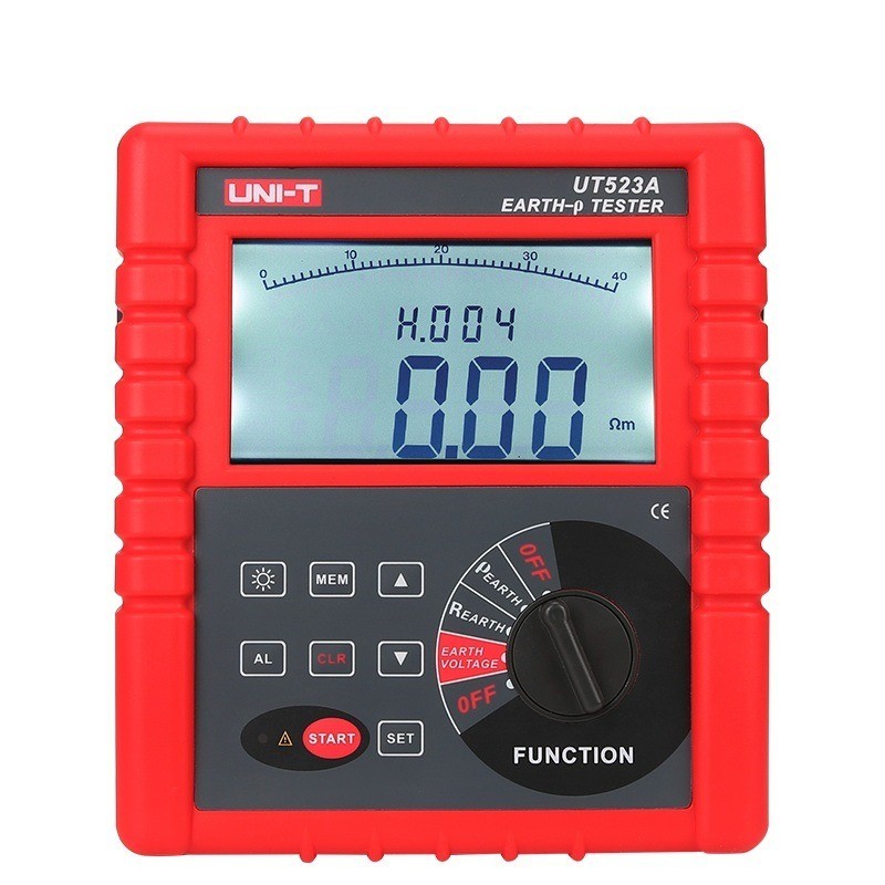
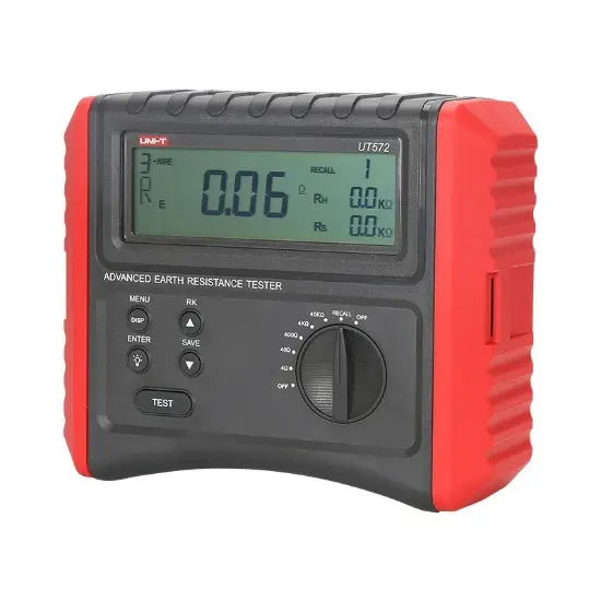
| Model NO. | UT572 Advance Earth Resistance Tester Digital Ground Resistance Test/Soil Resistivity Test Data Storage LCD Backlight |
| Earth resistance | 40kΩ ±(3%+5) |
| Soil resistivity | 40Ωm |
| Disturbance voltage | 50V DC/AC |
| Disturbance frequency | 40Hz~500Hz |
| Series | GR |
Feature
Certifications: CE, UKCA
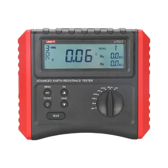
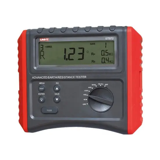
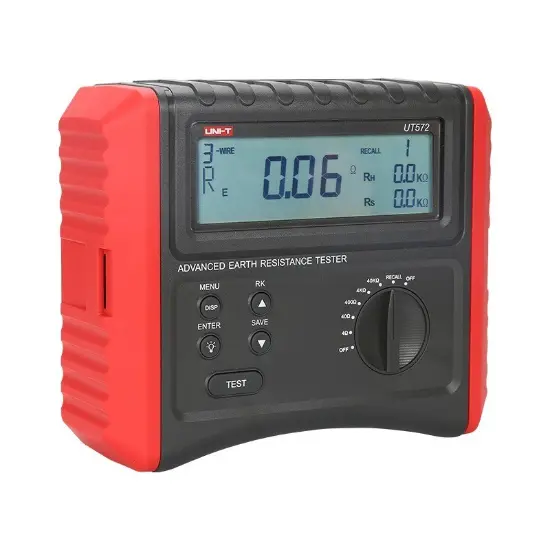
Large 4-digit LCD Display, 5s sampling time
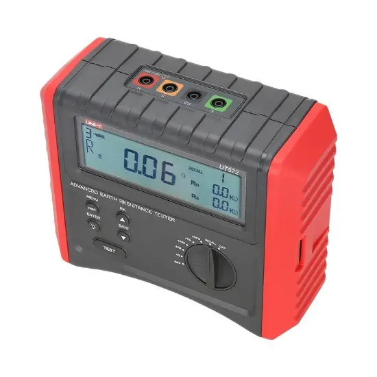
2/3/4-wire earth resistance and soil resistivity measurements
Selectable test frequencies (94Hz/128Hz)
Disturbance voltage (Ust) and frequency (Fst) measurement
Earth resistance, RH and RS measurements
LCD backlight; auto power off
Data hold
20 sets of data storage
Double insulation
Compensating resistance RK measurement
Specifications


How are ground resistance and soil resistivity measured?