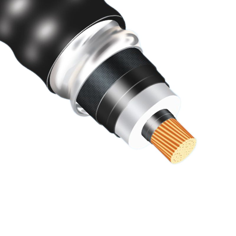
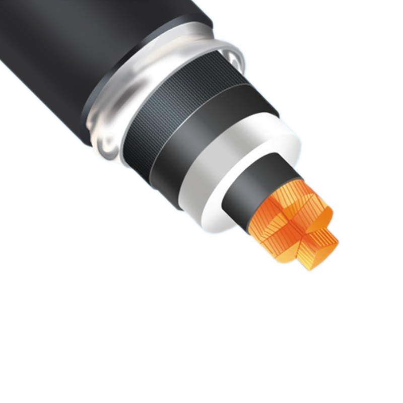
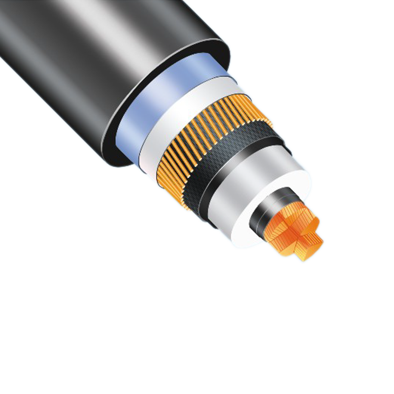
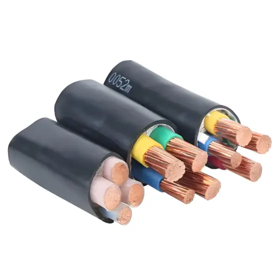
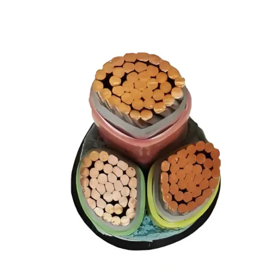
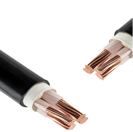
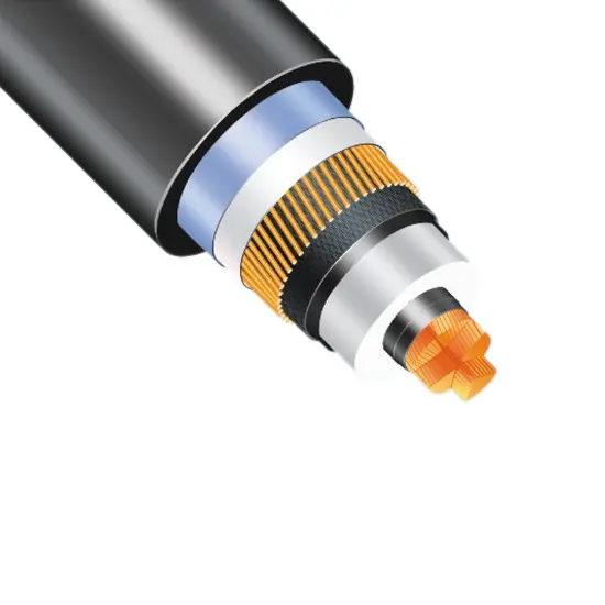
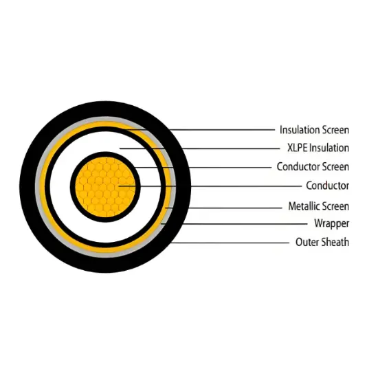
YJLW Series HV cross-linked cable
Key attributes
| Brand | Wone Store |
| Model NO. | YJLW Series cross-linked cable |
| Rated voltage | 110kV |
| number of core | 1-core |
| Nominal cross-sectional area | 240mm² |
| cable insulation structure | XLPE insulation&aluminum sheath&PE sheath |
| Conductor type | Al-core |
| Series | YJLW Series |
Product descriptions from the supplier
Overview
This productis suitable for 110-500kV power transmission and distribution system for thetransmission of electrical energy, low smoke no accounting for the flameretardant performance higher than the national standard, widely used inairports, nuclear power plants, key water control projects, high-risebuildings, Chemical, metallurgy, petroleum, traffic and other flame-retardantproperties demanding places.
Implementationstandards
66-132kV product implementationstandards: GB / T 11017 and GB / T 19666, the flame retardant properties inline with GB / T 18380 requirements;
220-500kV product implementationstandards: GB / T 18890 and GB / T 19666, the flame retardant properties inline with GB / T 18380 requirements.
Name and structure
Model |
Name | |
Cu-core |
Al-core |
|
YJLW02 |
YJLLW02 |
Cross - linked polyethylene insulated, corrugated aluminum or welded corrugated aluminum sheath and polyvinyl chloride sheathed power cable. |
YJLW03 |
YJLLW03 |
Cross - linked polyethylene insulated, corrugated aluminum or welded corrugated aluminum sheath and polyethylene sheathed power cable. |
YJLW02 - Z |
YJLLW02 - Z |
Cross - linked polyethylene insulated, corrugated aluminum or welded corrugated aluminum sheath and polyvinyl chloride sheathed longitudinal water blocking power cable. |
YJLW03 - Z |
YJLLW03 - Z |
Cross - linked polyethylene insulated, corrugated aluminum or welded corrugated aluminum sheath and polyethylene sheathed longitudinal water blocking power cable. |


parameters
66KV cross-linked power cable
Nominal cross- sectional area mm² |
Diameter of conductor mm |
Nominal thickness of insulation mm |
Thickness of aluminum sheath mm |
Thickness of over sheath mm |
Approximation outer diameter mm |
Approximate Weight(kg/km) |
|||
Copper (Cu)- PVC sheath |
Copper (Cu)- PE sheath |
Aluminum (Al)- PVC sheath |
Aluminum (Al)- PE sheath |
||||||
240 |
18.5 |
13.5 |
2.0 |
4.0 |
78 |
6598 |
6281 |
5128 |
4811 |
300 |
20.7 |
13.5 |
2.0 |
4.0 |
80 |
7329 |
7003 |
5487 |
5161 |
400 |
23.5 |
13.5 |
2.0 |
4.0 |
83 |
8317 |
7979 |
5961 |
5623 |
500 |
26.5 |
13.5 |
2.0 |
4.0 |
86 |
9546 |
9194 |
6520 |
6168 |
630 |
29.8 |
13.5 |
2.0 |
4.0 |
89 |
11113 |
10748 |
7201 |
6836 |
800 |
33.8 |
13.0 |
2.0 |
4.0 |
93 |
12912 |
12534 |
7902 |
7524 |
800F |
35.0 |
13.0 |
2.0 |
4.0 |
96 |
13614 |
13180 |
8604 |
8170 |
1000F |
39.2 |
13.0 |
2.0 |
4.5 |
102 |
15844 |
15390 |
9557 |
9103 |
1200F |
42.0 |
13.0 |
2.0 |
4.5 |
106 |
17641 |
17173 |
10313 |
9845 |
| 1400F | 46.0 | 13.0 | 2.0 | 4.5 | 109 | 19771 | 19287 | 11190 | 10706 |
| 1600F | 48.6 | 13.0 | 2.0 | 4.5 | 112 | 218.06 | 21308 | 12010 | 11512 |
110KV cross-linked power cable
Nominal cross-sectional area mm² |
Diameter of conductor |
Nominal thickness of insulation |
Thickness of aluminum sheath mm |
Thickness of over sheath mm |
Approximation outer diameter mm |
Approximate Weight(kg/km) |
|||
Copper (Cu)- PVC sheath |
Copper (Cu)- PE sheath |
Aluminum (Al)- PVC sheath |
Aluminum (Al)- PE sheath |
||||||
240 |
18.5 |
19.0 |
2.0 |
4.0 |
90 |
7967 |
7599 |
6497 |
6129 |
300 |
20.7 |
18.5 |
2.0 |
4.0 |
91 |
8603 |
8230 |
6761 |
6388 |
400 |
23.5 |
17.5 |
2.0 |
4.0 |
92 |
9363 |
8986 |
7007 |
6630 |
500 |
26.5 |
17.0 |
2.0 |
4.0 |
94 |
10492 |
10106 |
7466 |
7080 |
630 |
29.8 |
16.5 |
2.0 |
4.5 |
98 |
12203 |
11766 |
8291 |
7854 |
800 |
33.8 |
16.0 |
2.0 |
4.5 |
102 |
14034 |
13583 |
9024 |
8573 |
800F |
35.0 |
16.0 |
2.0 |
4.5 |
106 |
14542 |
14073 |
9532 |
9063 |
1000F |
39.2 |
16.0 |
2.3 |
4.5 |
110 |
17054 |
16565 |
10767 |
10278 |
1200F |
42.0 |
16.0 |
2.3 |
5.0 |
114 |
19136 |
18589 |
11808 |
11261 |
1400F |
46.0 |
16.0 |
2.3 |
5.0 |
118 |
21356 |
20787 |
12775 |
12206 |
1600F |
48.6 |
16.0 |
2.3 |
5.0 |
121 |
23434 |
22849 |
13638 |
13053 |
132KV cross-linked power cable
Nominal cross-sectional area mm² |
Diameter of conductor mm |
Nominal thickness of insulation |
Thickness of aluminum sheath mm |
Thickness of over sheath mm |
Approximation outer diameter |
Approximate Weight(kg/km) |
|||
Copper (Cu)- PVC sheath |
Copper (Cu)- PE sheath |
Aluminum (Al)- PVC sheath |
Aluminum (Al)- PE sheath |
||||||
240 |
18.5 |
19.5 |
2.0 |
4.0 |
91 |
8097 |
7725 |
6627 |
6255 |
300 |
20.7 |
19.0 |
2.0 |
4.0 |
92 |
8735 |
8357 |
6893 |
6515 |
400 |
23.5 |
19.0 |
2.0 |
4.0 |
96 |
9767 |
9377 |
7411 |
7021 |
500 |
26.5 |
19.0 |
2.0 |
4.0 |
99 |
11043 |
10641 |
8017 |
7615 |
630 |
29.8 |
19.0 |
2.0 |
4.5 |
103 |
12924 |
12464 |
9012 |
8552 |
800 |
33.8 |
18.0 |
2.0 |
4.5 |
106 |
14625 |
14156 |
9615 |
9146 |
800F |
35.0 |
18.0 |
2.0 |
4.5 |
109 |
15154 |
14666 |
10144 |
9656 |
1000F |
39.2 |
18.0 |
2.3 |
4.5 |
114 |
17701 |
17194 |
11414 |
10907 |
1200F |
42.0 |
18.0 |
2.3 |
5.0 |
118 |
19809 |
19243 |
12481 |
11915 |
1400F |
46.0 |
18.0 |
2.3 |
5.0 |
122 |
22048 |
21459 |
13467 |
12878 |
1600F |
48.6 |
18.0 |
2.3 |
5.0 |
125 |
24144 |
23539 |
14348 |
13743 |
220KV cross-linked power cable
Nominal cross-sectional area mm² |
Diameter of conductor |
Nominal thickness of insulation |
Thickness of aluminum sheath mm |
Thickness of over sheath mm |
Approximation outer diameter |
Approximate Weight(kg/km) |
|
Copper (Cu)- PVC sheath |
Copper (Cu)- PE sheath |
||||||
400 |
23.5 |
27.0 |
2.4 |
5.0 |
116 |
13141 |
12504 |
500 |
26.5 |
27.0 |
2.4 |
5.0 |
119 |
14515 |
13860 |
630 |
29.8 |
26.0 |
2.4 |
5.0 |
121 |
15887 |
15225 |
800 |
33.8 |
25.0 |
2.4 |
5.0 |
124 |
17683 |
17004 |
800F |
35.0 |
25.0 |
2.4 |
5.0 |
127 |
18285 |
17586 |
1000F |
39.2 |
24.0 |
2.6 |
5.0 |
130 |
20519 |
19805 |
1200F |
42.0 |
24.0 |
2.6 |
5.0 |
134 |
22490 |
21752 |
1400F |
46.0 |
24.0 |
2.6 |
5.0 |
137 |
24759 |
24001 |
1600F |
48.6 |
24.0 |
2.6 |
5.0 |
140 |
26920 |
26144 |
1800F |
52.0 |
24.0 |
2.8 |
5.0 |
144 |
29208 |
28413 |
2000F |
55.2 |
24.0 |
2.8 |
5.0 |
148 |
31602 |
30783 |
500KV cross-linked power cable
Nominal cross-sectional area mm² |
Diameter of conductor mm |
Nominal thickness of insulation mm |
Thickness of aluminum sheath mm |
Thickness of over sheath mm |
Approximation outer diameter |
Approximate Weight(kg/km) |
|
Copper(Cu)- PVC sheath |
Copper (Cu)- PE sheath |
||||||
800 |
33.8 |
34.0 |
2.9 |
6.0 |
150 |
20393 |
19688 |
800F |
35.0 |
34.0 |
2.9 |
6.0 |
152 |
20772 |
20047 |
1000F |
39.2 |
33.0 |
3.0 |
6.0 |
154 |
23057 |
22317 |
1200F |
42.0 |
33.0 |
3.0 |
6.0 |
158 |
25068 |
24310 |
1400F |
46.0 |
32.0 |
3.0 |
6.0 |
160 |
27419 |
26640 |
1600F |
48.6 |
32.0 |
3.1 |
6.0 |
163 |
29679 |
28876 |
1800F |
52.0 |
31.0 |
3.2 |
6.0 |
165 |
32036 |
31213 |
2000F |
55.2 |
31.0 |
3.2 |
6.0 |
169 |
34476 |
33636 |
2200F |
57.4 |
31.0 |
3.2 |
6.0 |
171 |
36318 |
35464 |
2500F |
61.5 |
31.0 |
3.3 |
6.0 |
175 |
39548 |
38671 |
800 |
33.8 |
34.0 |
2.9 |
6.0 |
150 |
20393 |
19688 |
Usefeatures
1、Maximum rated temperature
Long-term maximum allowable operatingconductor temperature: 90 ℃,Maximum operating temperature under short-timeoverload: 105 90 ℃,Maximum operating temperature under short circuit (shortcircuit duration 5 s): 250 ℃
2、Installation requirements
Cable laying shall not be restrictedby drop height; the ambient temperature for laying shall not be lower than 0 90 ℃;C,and if the ambient temperature is lower than 0 90 ℃, the cable shall bepre-heated.
2.1Minimum bending radius of cable
During cablelaying: 20D0; and Permanentinstallation: 15D0.
Note: D0 is measured outerdiameter of cable.
2.2Maximum allowable axial traction for cable installation, T (radial sidepressure at bend not being considered)
Conductor: T=K x Conductor section (kg)
Aluminum sheath:T x Aluminum sheath section(kg)
Where, the coefficient K=7kg/mm2for copper conductor and 4kg/mm2 for aluminum conductor and 2kg/mm2 for aluminum sheath.
2.3Maximumallowable side pressure when cable is bent, P
P=T/R≤500(kg/m), where T is axialtraction, and R is bending radius.

Related Products

Related Knowledges
-
 Main Transformer Accidents and Light Gas Operation Issues1. Accident Record (March 19, 2019)At 16:13 on March 19, 2019, the monitoring background reported a light gas action of No. 3 main transformer. In accordance with the Code for Operation of Power Transformers (DL/T572-2010), operation and maintenance (O&M) personnel inspected the on-site condition of No. 3 main transformer.On-site confirmation: The WBH non-electrical protection panel of No. 3 main transformer reported a Phase B light gas action of the transformer body, and the reset was ineff02/05/2026
 -
 Faults and Handling of Single-phase Grounding in 10kV Distribution LinesCharacteristics and Detection Devices for Single-Phase Ground Faults1. Characteristics of Single-Phase Ground FaultsCentral Alarm Signals:The warning bell rings, and the indicator lamp labeled “Ground Fault on [X] kV Bus Section [Y]” illuminates. In systems with a Petersen coil (arc suppression coil) grounding the neutral point, the “Petersen Coil Operated” indicator also lights up.Insulation Monitoring Voltmeter Indications:The voltage of the faulted phase decreases (in01/30/2026
 -
 Neutral point grounding operation mode for 110kV~220kV power grid transformersThe arrangement of neutral point grounding operation modes for 110kV~220kV power grid transformers shall meet the insulation withstand requirements of transformer neutral points, and shall also strive to keep the zero-sequence impedance of substations basically unchanged, while ensuring that the zero-sequence comprehensive impedance at any short-circuit point in the system does not exceed three times the positive-sequence comprehensive impedance.For 220kV and 110kV transformers in new constructi01/29/2026
 -
 Why Do Substations Use Stones, Gravel, Pebbles, and Crushed Rock?Why Do Substations Use Stones, Gravel, Pebbles, and Crushed Rock?In substations, equipment such as power and distribution transformers, transmission lines, voltage transformers, current transformers, and disconnect switches all require grounding. Beyond grounding, we will now explore in depth why gravel and crushed stone are commonly used in substations. Though they appear ordinary, these stones play a critical safety and functional role.In substation grounding design—especially when multiple gr01/29/2026
 -
 Why Must a Transformer Core Be Grounded at Only One Point? Isn't Multi-Point Grounding More Reliable?Why Does the Transformer Core Need to Be Grounded?During operation, the transformer core, along with the metal structures, parts, and components that fix the core and windings, are all situated in a strong electric field. Under the influence of this electric field, they acquire a relatively high potential with respect to ground. If the core is not grounded, a potential difference will exist between the core and the grounded clamping structures and tank, which may lead to intermittent discharge.I01/29/2026
 -
 Understanding Transformer Neutral GroundingI. What is a Neutral Point?In transformers and generators, the neutral point is a specific point in the winding where the absolute voltage between this point and each external terminal is equal. In the diagram below, pointOrepresents the neutral point.II. Why Does the Neutral Point Need Grounding?The electrical connection method between the neutral point and earth in a three-phase AC power system is called theneutral grounding method. This grounding method directly affects:The safety, reliabilit01/29/2026
Related Solutions
-
 Dedicated Vacuum Contactor Solution for Port Shore Power SystemsI. Background and ChallengesShore power systems have become core technical equipment for ports to reduce carbon emissions and noise pollution. However, these systems face two major challenges in the harsh operational environment of ports:Severe Environmental Corrosion: High humidity and salt spray in port areas cause serious corrosion to metal components and enclosures of electrical equipment, significantly impacting electrical lifespan and operational reliability.High Switching Requirements:09/13/2025
 -
 ABB Vacuum Contactor KC2 Power Supply System Technical Transformation PlanIssue OverviewThe 10kV air compressor starting system of a company utilizes the ABB vacuum contactor KC2 as the control component for the operating circuit. The dedicated wide-voltage power supply module paired with this contactor presents the following issues:Frequent failures: The power supply module fails to properly transition the voltage from 300V to 12V, resulting in fuse blowouts.Poor heat dissipation: Enclosed installation of the module leads to insufficient heat dissipation, acceler09/13/2025
 -
 Solution for Medium-Voltage Motor Control and Protection Using Vacuum Contactor-Fuse (VCF) in a Coal Conveying System1.Project BackgroundA coal conveying system comprises 15 belt conveyors driven by medium-voltage motors. The system operates under complex conditions, with motors often subjected to heavy loads and frequent starts. To address these challenges and achieve effective control and reliable protection during motor startup, the project comprehensively adopts Vacuum Contactor-Fuse (VCF) combination devices for the 6kV medium-voltage motor power distribution. This solution details the technical features,09/13/2025


