Methods of Voltage Control in Power System
The voltage within a power system is subject to variation in accordance with load fluctuations. Typically, the voltage is elevated during light - load periods and reduced under heavy - load conditions. To maintain the system voltage within acceptable limits, additional equipment is necessary. This equipment serves to increase the voltage when it is low and decrease it when it is overly high. The following are the methods employed in power systems for voltage control:
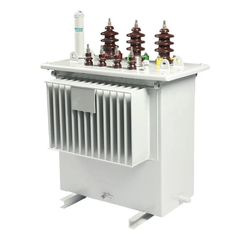
On - Load Tap Changing Transformer
Off - Load Tap Changing Transformer
Shunt Reactors
Synchronous Phase Modifiers
Shunt Capacitor
Static VAR System (SVS)
Controlling the system voltage with the aid of a shunt inductive element is referred to as shunt compensation. Shunt compensation is categorized into two types: static shunt compensation and synchronous compensation. In static shunt compensation, shunt reactors, shunt capacitors, and static VAR systems are utilized, while synchronous compensation makes use of synchronous phase modifiers. The methods for voltage control are elaborated in detail below.
Off - Load Tap Changing Transformer: In this approach, voltage control is achieved by altering the turns ratio of the transformer. Before changing the tap, the transformer must be disconnected from the power supply. Tap - changing of the transformer is predominantly carried out manually.
On - Load Tap Changing Transformer: This configuration is used to adjust the turns ratio of the transformer for regulating the system voltage while the transformer is delivering load. The majority of power transformers are equipped with on - load tap changers.
Shunt Reactor: A shunt reactor is an inductive current element connected between the line and the neutral. It compensates for the inductive current originating from transmission lines or underground cables. Shunt reactors are primarily used in long - distance Extra - High - Voltage (EHV) and Ultra - High - Voltage (UHV) transmission lines for reactive power control.
Shunt reactors are installed in the sending - end substation, receiving - end substation, and intermediate substations of long EHV and UHV lines. In long - distance transmission lines, shunt reactors are connected at intervals of approximately 300 km to limit the voltage at intermediate points.
Shunt Capacitors: Shunt capacitors are capacitors connected in parallel with the line. They are installed at receiving - end substations, distribution substations, and switching substations. Shunt capacitors inject reactive volt - amperes into the line and are typically arranged in three - phase banks.
Synchronous Phase Modifier: A synchronous phase modifier is a synchronous motor operating without a mechanical load. It is connected to the load at the receiving end of the line. By varying the excitation of the field winding, the synchronous phase modifier can either absorb or generate reactive power. It maintains a constant voltage under all load conditions and also improves the power factor.
Static VAR Systems (SVS): The static VAR compensator injects or absorbs inductive VAR into the system when the voltage deviates from the reference value, either higher or lower. In a static VAR compensator, thyristors are used as switching devices instead of circuit breakers. In modern systems, thyristor switching has replaced mechanical switching due to its faster operation and the ability to provide transient - free operation through switching control.