Fuse
Feature
The fuse is a simple and effective circuit protection element. When the current flow in the circuit is large, the melt in the fuse (such as the fuse) will be blown due to overheating, thus cutting off the circuit and preventing the equipment in the circuit from being damaged due to overcurrent. In the use of AC power, it can protect various electrical equipment, lines, etc. connected to the AC power supply. For example, in the home circuit, if a short circuit fault occurs in an electrical appliance, resulting in an instant increase in current, the fuse will fuse, avoid further expansion of the fault, and protect the safety of other electrical appliances and home wiring.
Type
Common glass tube fuses, ceramic fuses, etc., according to the fuse characteristics can be divided into fast fuses, slow fuses, etc., according to different application scenarios to choose the appropriate type of fuse.
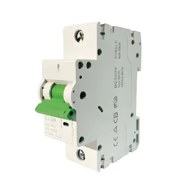
Contactor
Feature
Contactor is mainly used to control the on-off of AC circuit, especially in the control of high-power equipment widely used. It makes the contact close or break through the action of electromagnetic force, and can achieve remote control and frequent operation. For example, in the industrial environment, it is used to control the operation of the motor, such as start, stop and forward and reverse rotation. The contactor is composed of electromagnetic mechanism, contact system, arc extinguishing device, etc. When the coil of the contactor is energized, the generated electromagnetic force attracts the armature and makes the main contact close, thus closing the circuit; When the coil is powered off, the armature is reset under the action of the spring, the main contact is disconnected, and the circuit is cut off.
Application scenario
In the elevator control system, the operation of the motor is controlled by contactor to realize the elevator lifting operation. In air conditioning systems, contactors are also commonly used to control the start and stop of high-power components such as compressors.
Thermal relay
Feature
Thermal relay is a kind of relay specially used for overload protection of motor. It works based on the thermal effect of the current. When the electric motor is overloaded for a long time and the current continues to increase, the bimetal sheet inside the thermal relay will bend and deform due to heat. When the deformation reaches a certain degree, the contact of the thermal relay will act, thus cutting off the control circuit of the motor and realizing the overload protection of the motor. Because the motor will have a short starting current during the starting process, the thermal relay has a certain thermal inertia and will not misoperate due to the starting current.
Application scenario
Thermal relays are almost always used in the control circuits of various industrial motors, such as the motors in lathes, milling machines, drilling machines and other equipment in factories, to ensure the safety of the motors in the long-term operation process.
Current transformer and voltage transformer
Current transformer
Function: The large current is proportionally converted into a small current (usually 5A or 1A), in order to facilitate measuring instruments (such as ammeter), relay protection devices, etc., for measurement, protection and other operations. In alternating current systems, when large currents (such as those in high-voltage transmission lines) need to be measured, direct measurement is very dangerous and difficult to achieve, and current transformers can solve this problem. According to the principle of electromagnetic induction, the primary winding is connected in series in the measured circuit, and the secondary winding is connected to the measuring instrument or protection device.
Application scenario: Widely used in power system substations, power plants and other places, for monitoring the running current of lines and equipment.
Voltage transformer
Function: Convert high voltage to low voltage (such as 100V) proportionally, which is convenient for measuring equipment such as voltmeter and relay protection device to measure and monitor the voltage. For example, in a high-voltage transmission line, in order to measure the voltage of the line, the voltage transformer converts the high voltage to a low voltage suitable for the measurement and protection device operation. It is also based on the principle of electromagnetic induction, and the primary winding is connected to the circuit under test, and the secondary winding is connected to the measuring equipment.
Application scenario: It plays an indispensable role in the measurement, monitoring and protection of the power system.
Varistor
Feature
Varistor is a kind of nonlinear resistance element which is sensitive to voltage. Under normal voltage, it presents a very high resistance and has little effect on the circuit. When there is an overvoltage in the circuit (such as the surge voltage caused by lightning strikes or the peak voltage in the grid), the resistance value of the varistor will drop sharply, so as to release the overvoltage and protect the following circuit equipment from the damage of the overvoltage.
Application scenario
In the input end of AC power supply, such as computer power supply, TV power supply and other equipment, varistor is often installed to prevent lightning strikes and grid voltage fluctuations caused by the harm.
Common-mode inductance
Feature
Common mode inductors are used to suppress common mode interference in AC circuits. In electronic equipment, due to the presence of various electromagnetic interference sources, common mode interference signals (interference signals in the same direction that exist simultaneously on two or more wires) will be generated. The common mode inductor consists of two windings wound on the same iron core. When the common mode interference signal passes through the common mode inductor, the magnetic field generated by the current in the two windings enhances each other, thus producing a large inductive reactance to the common mode interference signal and preventing it from passing, while the normal differential mode signal (the signal in the opposite direction on the two wires) has less influence.
Application scenario
In switching power supply, communication equipment, computer motherboard and other circuits, it is used to improve the electromagnetic compatibility (EMC) of the circuit and reduce the impact of common mode interference on the performance of the equipment.