- Product
- Suppliers
- Manufacturers
- Solutions
- Free tools
- Knowledges
- Experts
- Communities
Search
-
Free tools
-
IEE Business offers free, AI-powered tools for electrical engineering design and power procurement budgeting: enter your parameters, click calculate, and get instant results for transformers, wiring, motors, power equipment costs, and more — trusted by engineers worldwide.
-
-
Support&Sponsorship
-
IEE-Business supports leading solutions, businesses, and experts - creating a platform where innovation meets valueOutstanding technical knowledgeJoin and share technical knowledge to earn money from sponsors.Excellent Business SolutionsJoin and create business solutions to earn money from sponsorsOutstanding Individual ExpertsBuild your talent show to sponsors, earn your future!
-
-
Community
-
Build your professional CommunityFind and connect with industry peers, potential partners, and decision-makers to grow your business.Expand Your Personal NetworkConnect with industry peers, potential partners, and decision-makers to accelerate your growth.Discover More OrganizationsExplore target companies, collaborators, and industry leaders to unlock new business opportunities.Join Diverse CommunitiesEngage in topic-driven discussions, industry exchanges, and resource sharing to amplify your impact.
-
-
Partner With Us
Partner
-
-
Join the lEE Business Partner ProgramEmpowering Business Growth -- From Technical Tools to Global Business Expansion
-
-
IEE Business
-
English
-
- English
- Afrikaans
- العربية
- Azərbaycan dili
- български
- বাংলা
- Català
- Cebuano
- čeština
- Dansk
- Deutsch
- Ελληνικά
- Esperanto
- Español
- Eesti keel
- Euskara
- دری
- فارسی
- suomi
- français
- Gaeilge
- Galego
- Hausa
- עברית
- हिन्दी
- Hrvatski
- magyar nyelv
- հայերեն
- Bahasa Indonesia
- Íslenska
- Italiano
- 日本語
- ქართული
- Қазақ тілі
- ಕನ್ನಡ
- 한국어
- Kurdî
- Latina
- Latviešu valoda
- македонски јазик
- Bahasa Melayu
- Malti
- नेपाली
- Nederlands
- Norsk
- ਪੰਜਾਬੀ
- polski
- پښتو
- Português
- Русский язык
- සිංහල
- Slovenščina
- српски језик
- Svenska
- Kiswahili
- தமிழ்
- తెలుగు
- ไทย
- Tagalog
- Türkçe
- українська мова
- اردو
- Oʻzbek tili
- Tiếng Việt
-
Outstanding technical knowledge
-
English
-
- English
- Afrikaans
- العربية
- Azərbaycan dili
- български
- বাংলা
- Català
- Cebuano
- čeština
- Dansk
- Deutsch
- Ελληνικά
- Esperanto
- Español
- Eesti keel
- Euskara
- دری
- فارسی
- suomi
- français
- Gaeilge
- Galego
- Hausa
- עברית
- हिन्दी
- Hrvatski
- magyar nyelv
- հայերեն
- Bahasa Indonesia
- Íslenska
- Italiano
- 日本語
- ქართული
- Қазақ тілі
- ಕನ್ನಡ
- 한국어
- Kurdî
- Latina
- Latviešu valoda
- македонски јазик
- Bahasa Melayu
- Malti
- नेपाली
- Nederlands
- Norsk
- ਪੰਜਾਬੀ
- polski
- پښتو
- Português
- Русский язык
- සිංහල
- Slovenščina
- српски језик
- Svenska
- Kiswahili
- தமிழ்
- తెలుగు
- ไทย
- Tagalog
- Türkçe
- українська мова
- اردو
- Oʻzbek tili
- Tiếng Việt
-
Outstanding technical knowledge


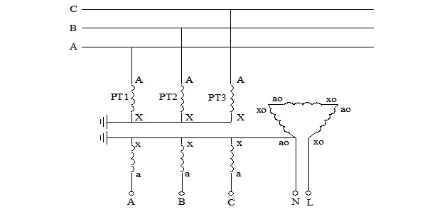
 As shown in Figure 1, when a different-frequency current is injected from the open delta side of the PT, a zero-sequence current is induced on the high-voltage side of the PT. Since this zero-sequence current has the same magnitude and direction in the three phases, it cannot flow through the power supply side or the load side and can only form a loop through the PT and the ground capacitance. Therefore, the schematic diagram of Figure 1 can be further simplified to the physical model shown in Figure 2.


