• Product
  • Suppliers
  • Manufacturers
  • Solutions
  • Free tools
  • Knowledges
  • Experts
  • Communities
Search


Impact of Grounding Resistance on Zero-Sequence Voltage Rise in Different Grounding Systems

Leon
Field: Fault Diagnosis
China

In an arc - suppression coil grounding system, the rising speed of the zero - sequence voltage is greatly affected by the value of the transition resistance at the grounding point. The larger the transition resistance at the grounding point, the slower the rising speed of the zero - sequence voltage.

In an ungrounded system, the transition resistance at the grounding point has basically no impact on the rising speed of the zero - sequence voltage.

Simulation Analysis: Arc - suppression Coil Grounding System

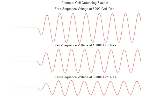
In the arc - suppression coil grounding system model, the influence on the rising speed of the zero - sequence voltage is analyzed by changing the value of the grounding resistance. From the zero - sequence voltage waveform in the figure, it can be seen that when the grounding resistances are 500 Ω, 1500 Ω, and 3000 Ω, the larger the resistance, the slower the rising speed of the zero - sequence voltage.

Fault initiation: The rising speed of the zero - sequence voltage makes the change of the sudden change amount not obvious. When using the sudden change amount of the zero - sequence voltage for initiation, the issue of parameter setting should be considered.

Fault diagnosis: When the criteria of the method adopted in fault diagnosis use the zero - sequence voltage data, the influence of the rising speed of the zero - sequence voltage on the diagnosis should be considered.

Simulation Analysis: Ungrounded System

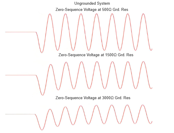
In the ungrounded system model, as can be seen from the zero-sequence voltage waveform in the figure, when the grounding resistances are 500 Ω, 1500 Ω, and 3000 Ω, the rising speed of the zero-sequence voltage shows no significant change with the increase of the resistance.

When a single-phase grounding fault occurs, some fault characteristic quantities differ significantly between the arc-suppression coil grounding system and the ungrounded system. Therefore, during fault diagnosis, it is necessary to distinguish and consider them separately, and analyze and solve problems in a specific manner based on the actual situation.

Give a tip and encourage the author!
Recommended
How to Maintain a PV Plant? State Grid Answers 8 Common O&M Questions(2)
1. On a scorching sunny day, do damaged vulnerable components need to be replaced immediately?Immediate replacement is not recommended. If replacement is necessary, it is advisable to do so in the early morning or late afternoon. You should contact the power station’s operation and maintenance (O&M) personnel promptly, and have professional staff go to the site for replacement.2. To prevent photovoltaic (PV) modules from being hit by heavy objects, can wire mesh protective screens be install
Encyclopedia
09/06/2025
How to Maintain a PV Plant? State Grid Answers 8 Common O&M Questions(1)
1. What are the common faults of distributed photovoltaic (PV) power generation systems? What typical problems may occur in various components of the system?Common faults include inverters failing to operate or start due to voltage not reaching the startup set value, and low power generation caused by issues with PV modules or inverters. Typical problems that may occur in system components are burnout of junction boxes and local burnout of PV modules.2. How to handle common faults of distributed
Leon
09/06/2025
Short Circuit vs. Overload: Understanding the Differences and How to Protect Your Power System
One of the main differences between a short circuit and an overload is that a short circuit occurs due to a fault between conductors (line-to-line) or between a conductor and earth (line-to-ground), whereas an overload refers to a situation where equipment draws more current than its rated capacity from the power supply.Other key differences between the two are explained in the comparison chart below.The term "overload" typically refers to a condition in a circuit or connected device. A circuit
Edwiin
08/28/2025
Leading vs Lagging Power Factor | Phase Difference Explained
Leading and lagging power factors are two key concepts related to the power factor in AC electrical systems. The main difference lies in the phase relationship between current and voltage: in a leading power factor, the current leads the voltage, whereas in a lagging power factor, the current lags behind the voltage. This behavior depends on the nature of the load in the circuit.What is Power Factor?Power factor is a crucial, dimensionless parameter in AC electrical systems, applicable to both s
Edwiin
08/26/2025
Seed Inquiry
Download
Get the IEE Business Application
Use the IEE-Business app to find equipment, obtain solutions, connect with experts, and participate in industry collaboration anytime, anywhere—fully supporting the development of your power projects and business.