How does a magnet affect an electron moving through a wire and producing an electrical current?

Encyclopedia
11/21/2024

How Do Magnets Affect the Movement of Electrons in a Wire and Generate Current?

Magnets can influence the movement of electrons in a wire and generate current through several mechanisms, primarily based on Faraday's law of electromagnetic induction and the Lorentz force. Here is a detailed explanation:

1. Faraday's Law of Electromagnetic Induction

  • Faraday's law of electromagnetic induction states that when the magnetic flux through a closed loop changes, an electromotive force (EMF) is induced in the loop, which can cause a current to flow. Specifically:

  • Changing Magnetic Field: When a magnet moves near a wire or when a wire moves in a magnetic field, the magnetic flux through the wire loop changes.

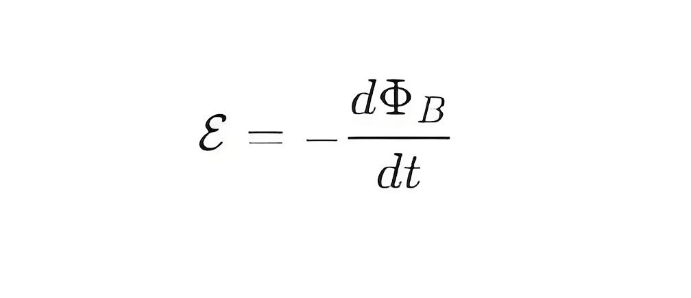
  • Induced EMF: According to Faraday's law, the change in magnetic flux induces an EMF E, given by the formula:

59e3cc2c7ed7cb9e6ee0b365d4799a10 (1).jpeg

where ΦB  is the magnetic flux and t is time.

Current: The induced EMF causes electrons to move in the wire, creating a current I. If the wire forms a closed loop, the current will continue to flow.

2. Lorentz Force

The Lorentz force describes the force experienced by a charged particle in a magnetic field. When electrons move in a wire, they experience the Lorentz force if a magnetic field is present. Specifically:

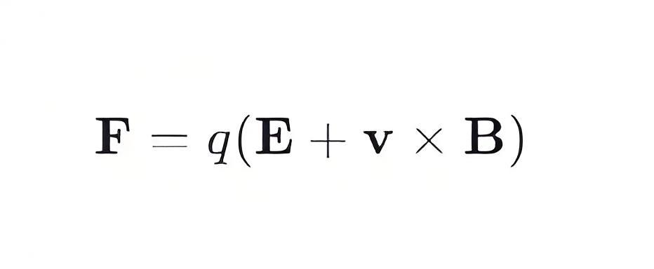
Lorentz Force Formula: The Lorentz force F is given by:

e2df22f96cd8170d529ea239709a3041.jpeg

where q is the charge, E is the electric field, v is the velocity of the charge, and B is the magnetic field.

Electron Motion in a Magnetic Field**: When electrons move in a magnetic field, the Lorentz force F=qv×B causes the electrons to deflect. This deflection changes the path of the electrons, affecting the direction and magnitude of the current.

3. Specific Applications

Generators

  • Principle: Generators utilize Faraday's law of electromagnetic induction by rotating magnets or wires to produce changing magnetic flux, which induces an EMF and current in the wires.

  • Application: Generators in power stations use large rotating magnets and wire coils to produce large-scale currents.

Motors

  • Principle: Motors use the Lorentz force to convert electrical energy into mechanical energy. When current flows through a wire in a magnetic field, the wire experiences a force that causes it to rotate.

  • Application: Motors are widely used in various mechanical devices, such as household appliances, industrial equipment, and vehicles.

Transformers

  • Principle: Transformers use Faraday's law of electromagnetic induction to transfer energy between primary and secondary coils through a changing magnetic field, thereby altering the voltage and current.

  • Application: Transformers are used in power transmission and distribution systems to step up or step down voltages.

4. Experimental Example

Faraday Disk Experiment

Setup: A metal disk is fixed on an axle, which is connected to a galvanometer. The metal disk is placed in a strong magnetic field.

Process: When the metal disk rotates, the magnetic flux through the disk changes, inducing an EMF according to Faraday's law, which causes a current to flow through the axle and the galvanometer.

Observation: The galvanometer shows a current flowing, demonstrating that the changing magnetic flux has generated an EMF.

Summary

Magnets affect the movement of electrons in a wire and generate current through Faraday's law of electromagnetic induction and the Lorentz force. A changing magnetic field induces an EMF in the wire, causing electrons to move and form a current. The Lorentz force deflects the path of moving electrons in a magnetic field, influencing the direction and magnitude of the current. These principles are widely applied in generators, motors, and transformers.

Encyclopedia

The Electricity Encyclopedia is dedicated to accelerating the dissemination and application of electricity knowledge and adding impetus to the development and innovation of the electricity industry.

Working Voltage in Power System
Working VoltageThe term "working voltage" refers to the maximum voltage that a device can withstand without sustaining damage or burning out, while ensuring the reliability, safety, and proper operation of both the device and associated circuits.For long-distance power transmission, the use of high voltage is advantageous. In AC systems, maintaining a load power factor as close to unity as possible is also economically necessary. Practically, heavy currents are more challenging to handle than hi
Encyclopedia
07/26/2025
Frequency division method for measuring grid-to-ground insulation parameters
The frequency division method enables the measurement of grid-to-ground parameters by injecting a current signal of a different frequency into the open delta side of the potential transformer (PT).This method is applicable to ungrounded systems; however, when measuring the grid-to-ground parameters of a system where the neutral point is grounded via an arc suppression coil, the arc suppression coil must be disconnected from operation beforehand. Its measurement principle is shown in Figure 1.As
Leon
07/25/2025
The insulation parameters of the power grid to ground are measured by the tuning method
The tuning method is suitable for measuring the ground parameters of systems where the neutral point is grounded via an arc suppression coil, but not applicable to ungrounded neutral point systems. Its measurement principle involves injecting a current signal with continuously varying frequency from the secondary side of the Potential Transformer (PT), measuring the returned voltage signal, and identifying the system's resonant frequency.During the frequency sweeping process, each injected heter
Leon
07/25/2025
Effect of Transition Resistance at the Grounding Point on the Rising Speed of Zero - sequence Voltage
In an arc - suppression coil grounding system, the rising speed of the zero - sequence voltage is greatly affected by the value of the transition resistance at the grounding point. The larger the transition resistance at the grounding point, the slower the rising speed of the zero - sequence voltage.In an ungrounded system, the transition resistance at the grounding point has basically no impact on the rising speed of the zero - sequence voltage.Simulation Analysis: Arc - suppression Coil Ground
Leon
07/24/2025
Inquiry
Download
IEE-Business is dedicated to serving the personnel in the global power industry.
Join IEE-Business, not only can you discover power equipment and power knowledge, but also canhnd like - minded friends!