• Product
  • Suppliers
  • Manufacturers
  • Solutions
  • Free tools
  • Knowledges
  • Experts
  • Communities
Search


Calibration of Voltmeter, Ammeter & Wattmeter using Potentiometer

Edwiin
Field: Power switch
China

Calibration is the process of verifying the accuracy of a result by comparing it with a standard value. In essence, it assesses the correctness of an instrument by contrasting it against a reference standard. This process enables us to identify errors in readings and make adjustments to voltages to achieve an ideal reading.

Calibration of Voltmeter
The circuit for the calibration of the voltmeter is shown in the figure below.

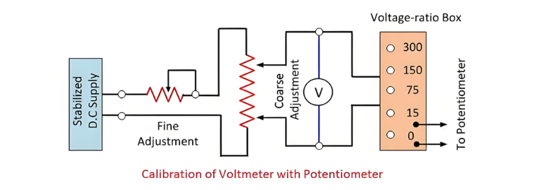
The circuit necessitates two rheostats: one serves to control the voltage, while the other is for fine - tuning. A voltage ratio box is employed to step - down the voltage to an appropriate level. The accurate value of the voltmeter is ascertained by measuring the voltage within the potentiometer's maximum possible range.

The potentiometer is capable of measuring the maximum achievable voltage values. If the readings of the potentiometer and the voltmeter do not match, negative or positive errors will manifest in the voltmeter's readings.

Calibration of Ammeter

The circuit for calibrating the ammeter is illustrated in the figure below.

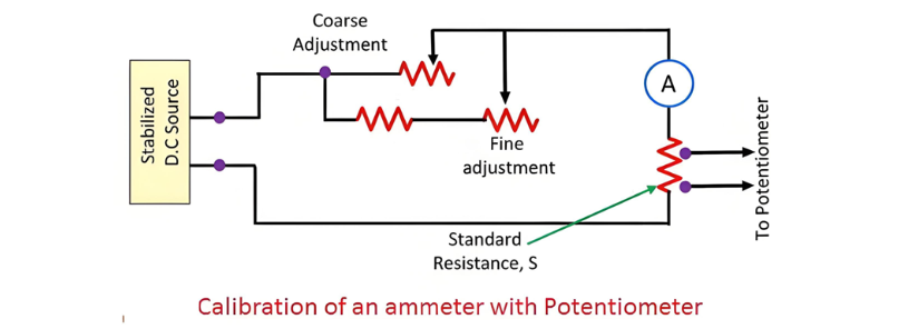
A standard resistance is connected in series with the ammeter that is to be calibrated. A potentiometer is utilized to measure the voltage across the standard resistor. The current flowing through the standard resistance is determined by the formula described below.

where:Vs is the voltage across the standard resistor, as measured by the potentiometer.S is the resistance value of the standard resistor.This approach to ammeter calibration is highly accurate. The reason lies in the fact that both the value of the standard resistance and the voltage measured by the potentiometer can be precisely determined by the measuring instruments.Calibration of WattmeterThe circuit employed for calibrating the wattmeter is depicted in the figure below.

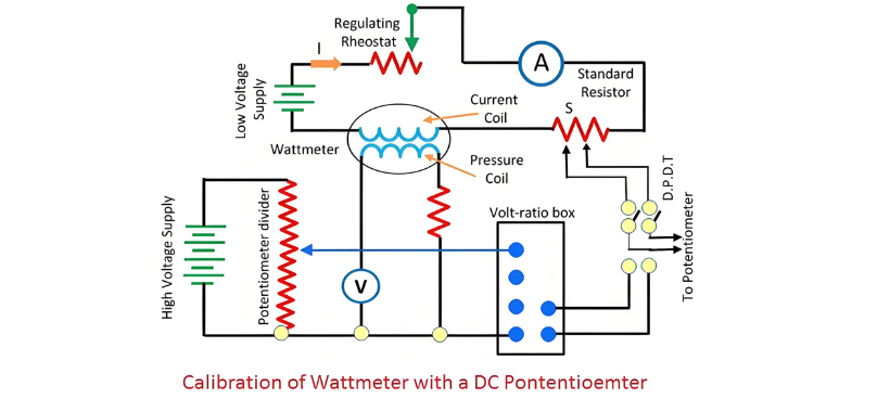
A standard resistance is connected in series with the wattmeter that requires calibration. A low - voltage power source supplies current to the current coil of the wattmeter. A rheostat is connected in series with the coil to regulate the current value.

The potential circuit is powered by the electrical supply. A volt - ratio box is utilized to reduce the voltage to a level that can be conveniently measured by the potentiometer. The actual values of voltage and current are measured using a double - pole double - throw switch. Subsequently, the accurate product of voltage and current (VI) is compared with the reading of the wattmeter.

Give a tip and encourage the author!

Recommended

Why Must a Transformer Core Be Grounded at Only One Point? Isn't Multi-Point Grounding More Reliable?
Why Does the Transformer Core Need to Be Grounded?During operation, the transformer core, along with the metal structures, parts, and components that fix the core and windings, are all situated in a strong electric field. Under the influence of this electric field, they acquire a relatively high potential with respect to ground. If the core is not grounded, a potential difference will exist between the core and the grounded clamping structures and tank, which may lead to intermittent discharge.I
01/29/2026
Understanding Transformer Neutral Grounding
I. What is a Neutral Point?In transformers and generators, the neutral point is a specific point in the winding where the absolute voltage between this point and each external terminal is equal. In the diagram below, pointOrepresents the neutral point.II. Why Does the Neutral Point Need Grounding?The electrical connection method between the neutral point and earth in a three-phase AC power system is called theneutral grounding method. This grounding method directly affects:The safety, reliabilit
01/29/2026
Voltage Imbalance: Ground Fault, Open Line, or Resonance?
Single-phase grounding, line break (open-phase), and resonance can all cause three-phase voltage unbalance. Correctly distinguishing among them is essential for rapid troubleshooting.Single-Phase GroundingAlthough single-phase grounding causes three-phase voltage unbalance, the line-to-line voltage magnitude remains unchanged. It can be classified into two types: metallic grounding and non-metallic grounding. Inmetallic grounding, the faulted phase voltage drops to zero, while the other two phas
11/08/2025
Composition and Working Principle of Photovoltaic Power Generation Systems
Composition and Working Principle of Photovoltaic (PV) Power Generation SystemsA photovoltaic (PV) power generation system is primarily composed of PV modules, a controller, an inverter, batteries, and other accessories (batteries are not required for grid-connected systems). Based on whether it relies on the public power grid, PV systems are divided into off-grid and grid-connected types. Off-grid systems operate independently without relying on the utility grid. They are equipped with energy-s
10/09/2025
Send inquiry
+86
Click to upload file
Download
Get the IEE Business Application
Use the IEE-Business app to find equipment, obtain solutions, connect with experts, and participate in industry collaboration anytime, anywhere—fully supporting the development of your power projects and business.