
The assembly of insulated conductors housed within the slots of an armature is known as an armature winding. This crucial component serves as the site where power conversion occurs. In a generator, the armature winding facilitates the transformation of mechanical power into electrical energy. Conversely, in an electric motor, it enables the conversion of electrical energy into mechanical energy, thereby playing a pivotal role in the operation of both electrical machines.
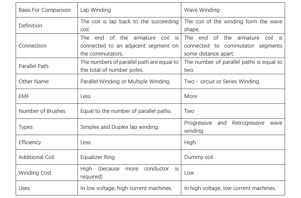
The armature winding can be mainly categorized into two distinct types: lap winding and wave winding. One of the most prominent differences between them lies in the connection mode of the coil ends. In lap winding, the ends of each coil are linked to adjacent commutator segments. Conversely, in wave winding, the ends of the armature coils are connected to commutator segments that are spaced apart from each other.
Content: Lap V/S Wave Winding
Comparison Chart
Definition
Key Differences
Comparison Chart
Definition of Lap Winding
In lap winding, consecutive coils are arranged such that they overlap one another. The finishing end of one coil connects to a specific commutator segment, while the starting end of the next coil—positioned under the influence of an adjacent magnetic pole (of opposite polarity)—is also joined to the same commutator segment. This configuration creates a parallel path structure, where each coil’s connection “laps back” to the adjacent segment, hence the name “lap winding.” This arrangement allows for multiple parallel current paths, making it suitable for applications requiring high current capacity and low voltage output.
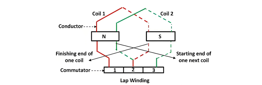
Configuration of Lap Winding
In lap winding, the conductors are interconnected such that the number of parallel paths (a) corresponds to the number of poles (P) in the machine. For a machine with P poles and Z armature conductors, there will be P parallel paths, each containing Z/P conductors connected in series. The number of brushes required equals the number of parallel paths, with half of the brushes serving as positive terminals and the other half as negative terminals.
Lap winding is further categorized into two subtypes:
Simplex Lap Winding: Features a = P, meaning the number of parallel paths equals the number of poles.
Duplex Lap Winding: Characterized by a = 2P, where the number of parallel paths is twice the number of poles.
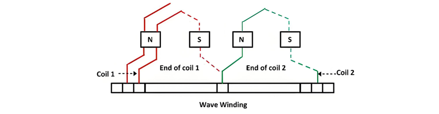
Definition of Wave Winding
In wave winding, one end of a coil connects to the starting end of another coil that shares the same magnetic polarity. This arrangement forms a continuous, wave-like pattern, giving the winding its name. The conductors in wave winding are divided into two parallel paths, each containing Z/2 conductors in series. Consequently, wave winding requires only two brushes—one positive and one negative—to align with the two parallel paths.
This configuration makes wave winding particularly suitable for high-voltage, low-current applications, as the series connection of conductors increases the total induced voltage while maintaining a manageable current through the parallel paths.
Key Differences Between Lap and Wave Winding
Coil Arrangement
In lap winding, coils are configured such that each coil laps back onto the next, creating an overlapping pattern. On the other hand, wave winding features coils connected in a wave - like formation, giving it a distinct and continuous shape.
Commutator Connection
For lap winding, the ends of the armature coils are connected to adjacent commutator segments. In contrast, in wave winding, the ends of the armature coils are attached to commutator segments that are spaced apart from each other, resulting in a different electrical connection pattern.
Number of Parallel Paths
Lap winding has the number of parallel paths equal to the total number of poles of the machine. For example, if a machine has P poles, there will be P parallel paths. In wave winding, regardless of the number of poles, the number of parallel paths is always two.
Connection Type
Lap winding is often referred to as parallel winding due to the parallel connection of its coils, which allows for multiple current - carrying paths. Conversely, wave winding has coils connected in series, earning it the name series winding. This difference in connection type significantly impacts the electrical characteristics of the two winding methods.
Electromotive Force (emf)
The emf generated in lap winding is generally lower compared to that of wave winding. This is a direct result of the different electrical configurations and the number of series - connected conductors in each type of winding.
Additional Components Required
Lap winding often requires equalizers to facilitate better commutation, which is the process of converting alternating current (AC) induced in the coils to direct current (DC) at the output. Wave winding, on the other hand, needs dummy coils to provide mechanical balance to the armature, ensuring smooth operation of the machine.
Number of Brushes
The number of brushes in lap winding is equal to the number of parallel paths, which means it can vary depending on the number of poles. In wave winding, the number of brushes is fixed at two, corresponding to the two parallel paths.
Efficiency
Wave winding typically exhibits higher efficiency compared to lap winding. This is due to factors such as lower electrical losses and more optimized current - flow patterns in the series - connected coils of wave winding.
Sub - types
Lap winding has subtypes like simplex and duplex. In simplex winding, the number of parallel paths is equal to the number of poles, while in duplex winding, the number of parallel paths is twice the number of poles. Wave winding, conversely, has subtypes such as progressive and retrogressive, which are differentiated by the direction of coil connection in the wave - like pattern.
Cost
The cost of lap winding is generally higher than that of wave winding. This is mainly because lap winding requires more conductors due to its parallel - coil configuration and the associated need for additional connections and components.
Application
Lap winding is commonly used in low - voltage, high - current electrical machines, such as large DC generators for battery charging or some types of electric traction motors. Wave winding, on the other hand, is more suitable for high - voltage, low - current machines, like certain DC generators used in power transmission systems.
In wave winding, dummy coils are incorporated solely to provide mechanical balance to the armature, ensuring smooth and stable operation of the machine. Unlike active coils, dummy coils do not participate in the electrical circuit and are therefore not connected to the commutator or involved in generating electromotive force (EMF). Their primary function is to counteract any imbalance caused by the winding arrangement, which typically leaves unused slots in the armature core when the number of coils does not align perfectly with the pole pitch. By filling these slots with dummy coils, the armature’s rotational symmetry is maintained, minimizing vibration and wear during operation.


