Key Considerations in Transformer Specification

As a professional involved in formulating technical specifications for power transformers, I recognize that defining these specifications is a critical step to ensure equipment reliability, efficiency, and compliance with international standards like IEC 60076. A comprehensive specification must clearly outline all parameters to avoid operational inefficiencies, technical discrepancies, and potential failures. Below, from my professional perspective, are the core considerations in formulating specifications and selecting key parameters.
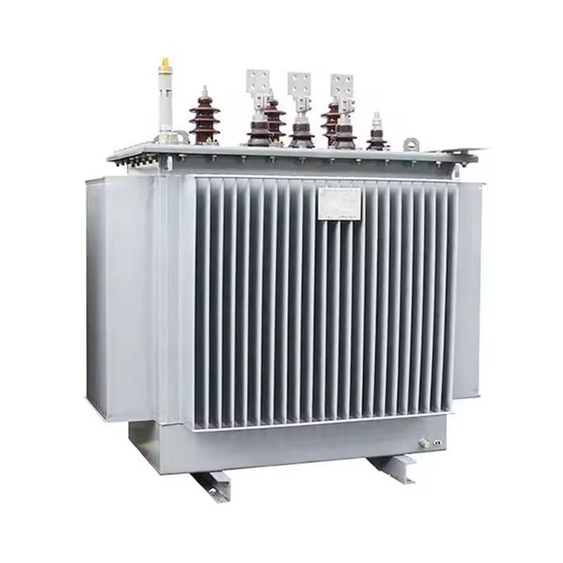
I. Determination of Rated Power and Voltage Levels
Precisely defining rated power and voltage levels is fundamental in specification development. We must set an appropriate rated power (in MVA or kVA) based on actual requirements to ensure the transformer can carry the expected load without excessive losses or overheating. Meanwhile, we clearly define primary and secondary voltage levels to match system needs, and specify the transformer's application scenario (transmission, distribution, or industrial) to ensure the rated voltage aligns with the system design.
II. Control of Insulation and Dielectric Performance
Insulation level and dielectric strength directly impact the transformer's ability to withstand overvoltages, switching transients, and lightning impulses. We strictly design insulation coordination according to the equipment's highest voltage (Um) and basic insulation level (BIL) requirements to ensure safe operation under expected grid conditions. In material selection and parameter setting, we rationally choose insulation materials and determine dielectric strength to prevent insulation failures and extend equipment lifespan.
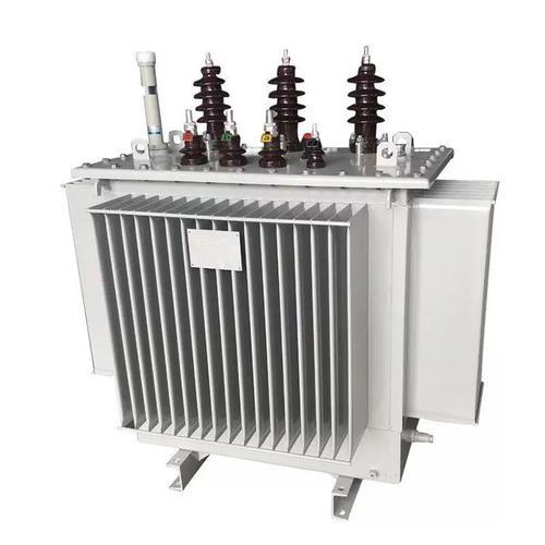
III. Setting Cooling Methods and Temperature Rise Limits
Defining cooling methods and temperature rise limits is essential for ensuring safe transformer operation. Common cooling methods include ONAN, ONAF, OFAF, and OFWF. We select a suitable cooling method for the transformer based on load and environmental conditions, and specify corresponding temperature rise limits.
IV. Ensuring Short-Circuit and Mechanical Performance
Short-circuit strength and mechanical robustness determine the transformer's reliability during electrical faults. We precisely set the short-circuit impedance to regulate fault currents and maintain system stability, while ensuring the transformer's windings and core are structurally robust to withstand high mechanical stresses during faults, avoiding structural and functional damage.
V. Clarification of Efficiency and Loss Parameters
Efficiency and losses are key factors in transformer selection. We comprehensively cover no-load losses, load losses, and overall efficiency under different loading conditions in the specification. Considering the transformer's continuous operation, we optimize parameters to reduce energy losses, achieve life-cycle cost control, and balance initial investment with energy efficiency.
VI. Design of Voltage Regulation and Tapping Arrangements
To enable the transformer to adapt to grid fluctuations, we precisely specify voltage regulation and tapping arrangements. We define the use of on-load tap changers (OLTC) or off-load tap changers (DETC), and detail the number of tapping steps, voltage adjustment range, and tap changer type to ensure voltage stability.
VII. Adaptation to Environmental and Site Conditions
When formulating specifications, we carefully consider environmental and site-specific conditions, such as installation altitude, temperature, humidity, pollution levels, and seismic activity—factors that directly impact transformer design and operation. For extreme applications, we add special design requirements, such as high-altitude insulation adjustments, corrosion-resistant materials, or upgraded cooling systems.
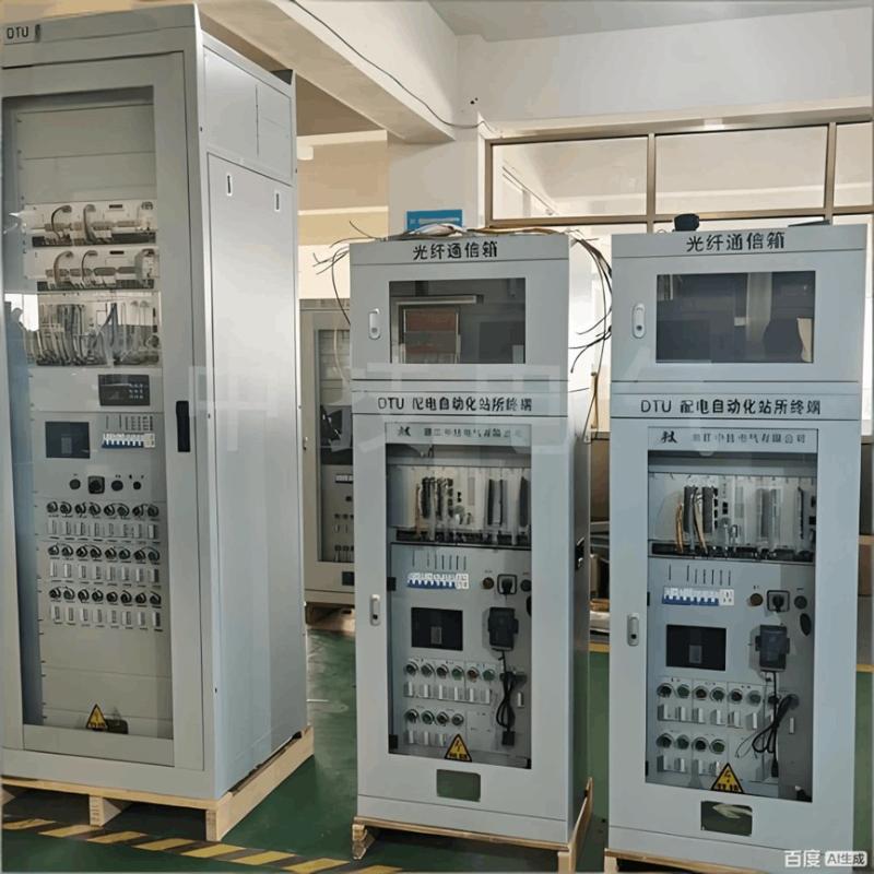
VIII. Standardization of Nameplate and Operation & Maintenance Information
Specifications must include detailed nameplate information, covering transformer type, rated power, voltage parameters, connection symbols, cooling method, insulation class, impedance, and manufacturer details, to support equipment identification, operation, and maintenance. Meanwhile, we clarify transportation and installation procedures (including weight limits, lifting arrangements, and storage requirements), as well as guidelines for preventive maintenance, oil analysis, and periodic inspections to ensure long-term reliability.
IX. Selection of System Voltage and Power Ratings per IEC 60076
Selecting system voltage and power ratings is central to specification development. This directly affects the transformer's capability to handle loads, voltage fluctuations, and efficiency/reliability in the grid, requiring strict compliance with IEC 60076.
(I) Selection of Voltage Ratings
Combining system voltage and grid operation requirements, we select the transformer's rated voltage (Ur) per IEC 60076-1 to match the system's highest voltage, ensuring insulation coordination and dielectric strength. We define the highest voltage for equipment (Um) to ensure the insulation system is suitable and prevent dielectric breakdown; determine each winding's rated voltage with reference to standard preferred values to enhance compatibility with grid equipment; and select the voltage ratio to meet system voltage transformation needs (e.g., 132/11 kV for transmission-to-distribution voltage conversion). Additionally, per IEC 60076-3, we consider the impact of system voltage on insulation coordination, configuring more robust insulation for transformers operating at higher voltages to withstand lightning and switching overvoltages.
(II) Selection of Power Ratings
Per IEC 60076, the transformer's rated power (Sr, in MVA or kVA) is determined by integrating system requirements, load conditions, and efficiency. We clarify rated power distribution (both windings of a two-winding transformer have the same rating, while multi-winding transformers may have different ratings for each winding); consider load cycles (normal, emergency, and short-term overload); and correlate cooling methods with power ratings (e.g., different ratings for ONAN and ONAF cooling) to ensure safe operation within specified temperature rise limits.
(III) Factors Influencing Parameter Selection
Grid configuration and stability, load growth and expansion, voltage regulation and tapping needs, and short-circuit considerations all impact the selection of voltage and power ratings. We ensure the transformer adapts to grid voltage and short-circuit withstand capability; reserve capacity for load growth to avoid overloading; configure tap changers as needed to maintain voltage stability; and rationally select short-circuit impedance to limit fault currents and ensure voltage stability, following IEC 60076-5 requirements for short-circuit withstand capability.