Rotor Earth Fault Protection

Encyclopedia
09/10/2024

Rotor Earth Fault Protection Definition


Rotor earth fault protection involves methods to detect and fix faults in the rotor’s field winding to prevent damage.


Rotor Earth Fault Protection Types


  • Potentiometer method

  • AC injection method

  • DC injection method


Potentiometer Method


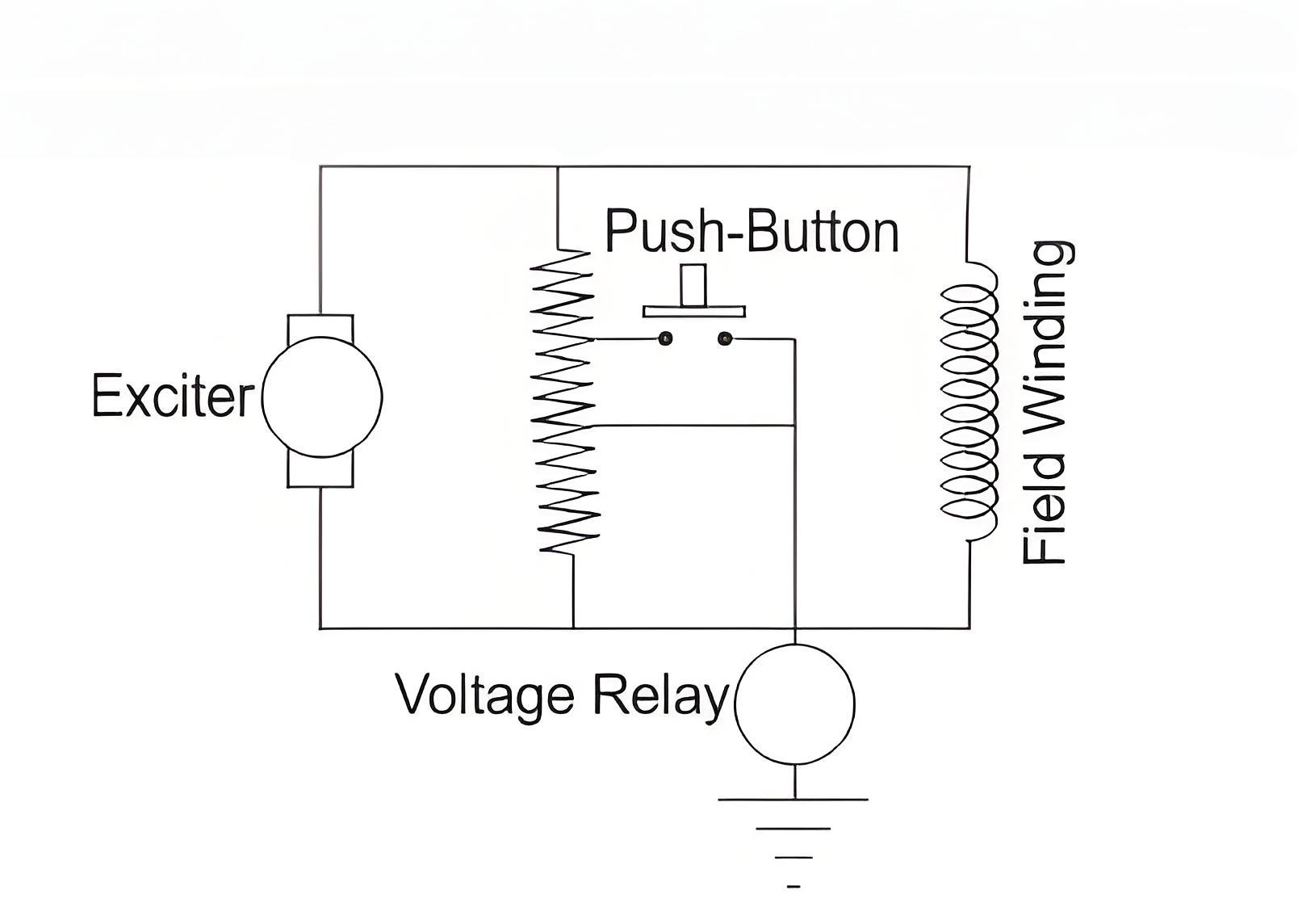
The scheme is very simple. Here, one resistor of suitable value is connected across the field winding as well as across exciter. The resistor is centrally tapped and connected to the ground via a voltage sensitive relay.


As it is seen in the figure below, any earth fault in the field winding as well as exciter circuit closes the relay circuit through earthed path. At the same time the voltage appears across the relay due to potentiometer action of the resistor.


This simple method of rotor earth fault protection has a major disadvantage. It can only detect earth faults that occur at any point except the center of the field winding.


47155bf7813b8ad09e3137f9b45222f5.jpeg


AC Injection Method


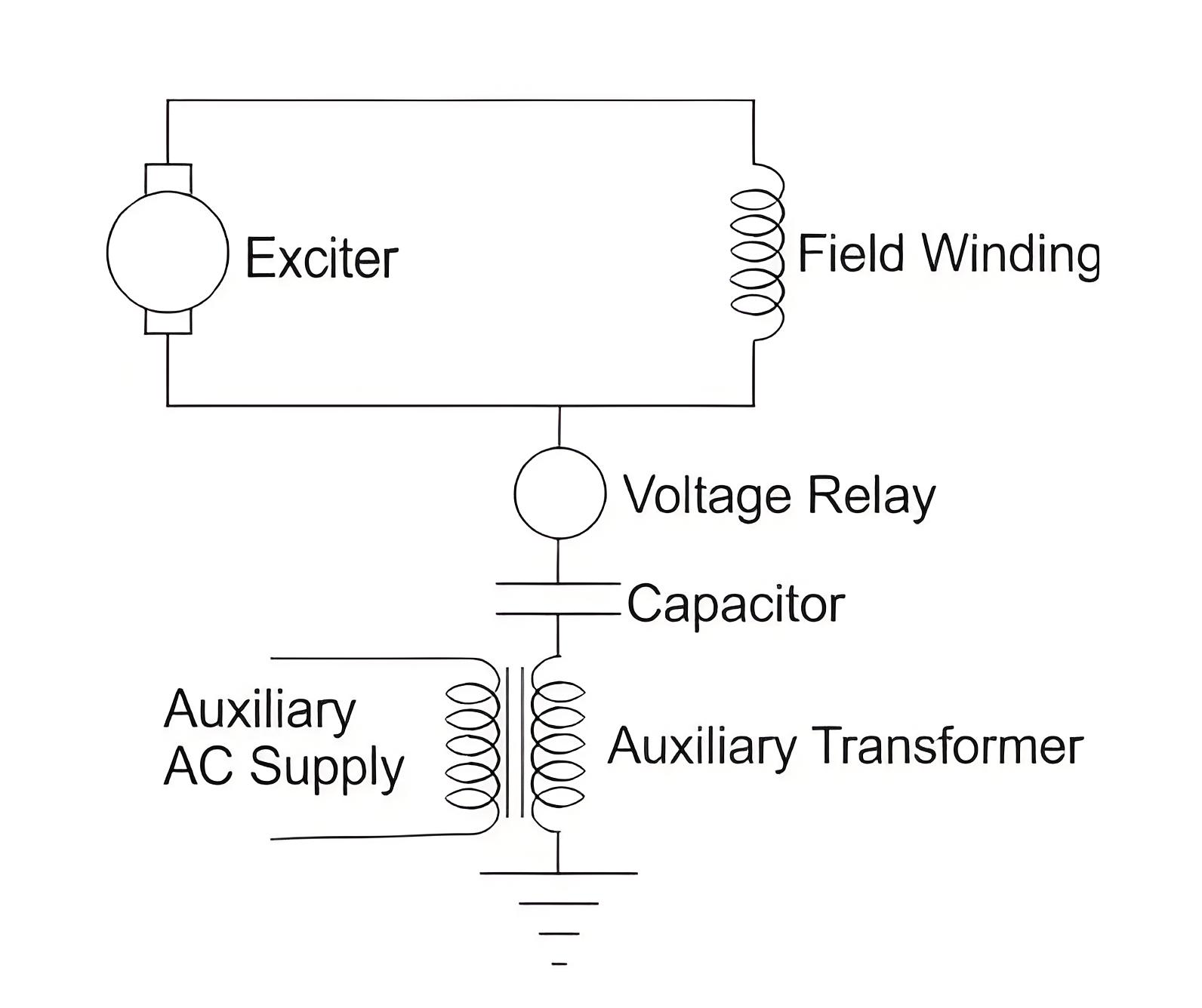
Here, one voltage sensitive relay is connected at any point of the field and exciter circuit. Other terminal of the voltage sensitive relay is connected to the ground by a capacitor and secondary of one auxiliary transformer as shown in the figure below.


Here, if any earth fault occurs in the field winding or in the exciter circuit, the relay circuit gets closed via earthed path and hence secondary voltage of the auxiliary transformer will appear across the voltage sensitive relay and the relay will be operated.


c04136a72ff865b5d6d62acd7f59299e.jpeg


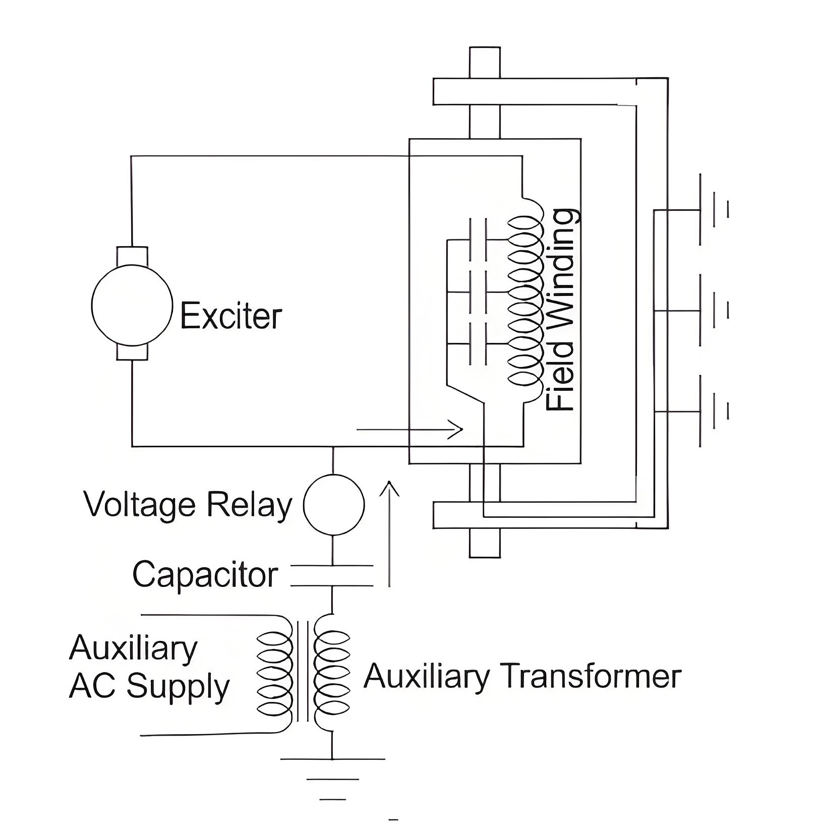
The main disadvantage of this system is, there would always be a chance of leakage current through the capacitors to the exciter and field circuit. This may cause unbalancing in magnetic field and hence mechanical stresses in the machine bearings.


Another disadvantage of this scheme is that it relies on a separate voltage source for the relay’s operation. Thus, rotor protection becomes inactive if there is a failure in the AC supply.


b9cd23495952c1c6f099204300b641fb.jpeg


DC Injection Method


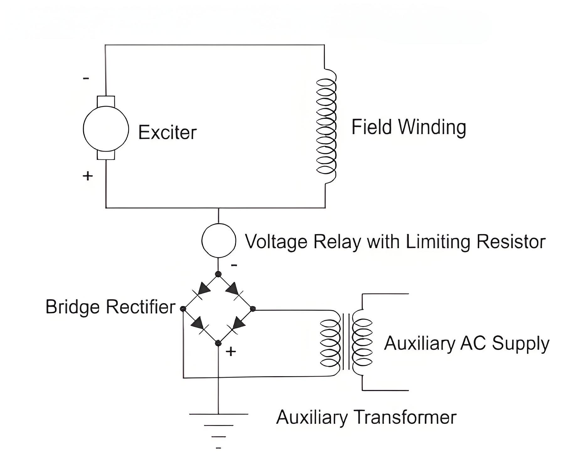
The DC injection method eliminates the leakage current problem found in the AC injection method. In this method, one terminal of a DC voltage-sensitive relay is connected to the positive terminal of the exciter, and the other terminal is connected to the negative terminal of an external DC source. This DC source is provided by an auxiliary transformer with a bridge rectifier, with its positive terminal grounded.


It is also seen from the figure below that at the event of any field earth fault or exciter earth fault, the positive potential of the external DC source will appear to the terminal of the relay which was connected to the positive terminal of the exciter. In this way the rectifier output voltage appears across the voltage relay and hence it is operated.


72ac35e5c63ebf3e743e2b6152b3365e.jpeg


Importance of Detection


Detecting and rectifying rotor earth faults is crucial for preventing unbalanced magnetic fields and mechanical damage in alternators.


Encyclopedia

The Electricity Encyclopedia is dedicated to accelerating the dissemination and application of electricity knowledge and adding impetus to the development and innovation of the electricity industry.

What is Voltage Stability in Power Systems?
Definition of Voltage StabilityVoltage stability in a power system is defined as the ability to maintain acceptable voltages at all buses under both normal operating conditions and after being subjected to a disturbance. In normal operation, the system’s voltages remain stable; however, when a fault or disturbance occurs, voltage instability may arise, leading to a progressive and uncontrollable voltage decline. Voltage stability is sometimes referred to as "load stability."Voltage instability c
Encyclopedia
07/26/2025
What is Dual Trace Oscilloscope?
What is Dual Trace Oscilloscope?DefinitionA dual-trace oscilloscope uses a single electron beam to generate two separate traces, each deflected by an independent input source. To produce these two traces, it primarily employs two operating modes—alternate mode and chopped mode—controlled by a switch.Purpose of a Dual-Trace OscilloscopeWhen analyzing or studying multiple electronic circuits, comparing their voltage characteristics is often critical. While one could use multiple oscilloscopes for
Encyclopedia
07/25/2025
What is Cathode Ray Oscilloscope (CRO)?
What is Cathode Ray Oscilloscope (CRO)?DefinitionA cathode ray oscilloscope (CRO) is an electrical instrument for measuring, analyzing and visualizing waveforms and other electronic/electrical phenomena. As a high - speed X - Y plotter, it shows an input signal against another signal or time. Capable of analyzing waveforms, transient phenomena and time - varying quantities across a wide frequency range (from very low to radio frequencies), it mainly operates on voltage. Other physical quantities
Edwiin
07/25/2025
Analysis of the Technical Characteristics of Online Monitoring for Medium-Voltage Switchgear Status
With the increasing complexity of power system operation environment and the deepening of power system reform, traditional power grids are accelerating the transformation to smart grids. The goal of equipment condition-based maintenance is achieved through real-time perception of equipment status by new sensors, reliable communication via modern network technology, and effective monitoring by background expert systems.I. Analysis of Condition-based Maintenance StrategyCondition-based Maintenance
Oliver Watts
06/11/2025
Inquiry
Download
IEE-Business is dedicated to serving the personnel in the global power industry.
Join IEE-Business, not only can you discover power equipment and power knowledge, but also canhnd like - minded friends!