What is Dual Trace Oscilloscope?

Encyclopedia
07/25/2025

What is Dual Trace Oscilloscope?

Definition

A dual-trace oscilloscope uses a single electron beam to generate two separate traces, each deflected by an independent input source. To produce these two traces, it primarily employs two operating modes—alternate mode and chopped mode—controlled by a switch.

Purpose of a Dual-Trace Oscilloscope

When analyzing or studying multiple electronic circuits, comparing their voltage characteristics is often critical. While one could use multiple oscilloscopes for such comparisons, synchronizing the sweep triggering of each device is highly challenging. A dual-trace oscilloscope addresses this by generating two traces using a single electron beam, enabling convenient and accurate simultaneous analysis.

Block Diagram and Working Principle of a Dual-Trace Oscilloscope

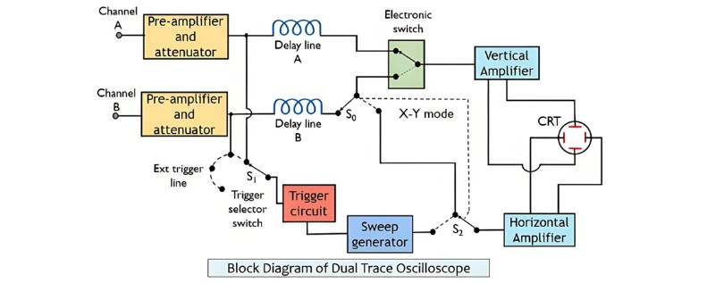
The block diagram of a dual-trace oscilloscope is shown below:

Measurement.jpg

As shown in the figure above, the oscilloscope features two independent vertical input channels, labeled A and B.Each input is separately fed into a preamplifier and attenuator stage. The outputs from these two stages are then routed to an electronic switch, which allows only one channel’s input to pass through to the vertical amplifier at any given time.The circuit also includes a trigger selector switch, enabling triggering via either channel A, channel B, or an externally applied signal.

A horizontal amplifier supplies signals to the electronic switch, with the source determined by switches S0 and S2—either the sweep generator or channel B. This setup allows vertical signals from channel A and horizontal signals from channel B to be sent to the CRT, enabling X-Y mode operation for precise X-Y measurements.

The oscilloscope’s operating modes are selected via front-panel controls, allowing users to display traces from channel A alone, channel B alone, or both channels simultaneously. As previously noted, dual-trace oscilloscopes operate in two key modes:

Alternate Mode

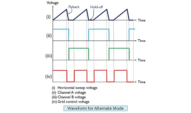
When alternate mode is activated, the electronic switch alternates between the two channels, switching at the start of each new sweep. The switching rate is synchronized with the sweep rate, ensuring each channel’s trace is displayed in separate sweeps: channel A’s trace appears in the first sweep, followed by channel B’s trace in the next.

Switching between channels occurs during the sweep flyback period, when the electron beam is invisible—preventing any visible disruption to the traces. This results in a complete sweep signal from one vertical channel being displayed, followed by a full sweep from the other channel in the subsequent cycle.

The waveform output of the oscilloscope operating in alternate mode is shown in the figure below:

Measurement..jpg

This mode preserves the correct phase relationship between signals from channels A and B. However, it has a drawback: the display shows the two signals as occurring at different times, even though they are actually simultaneous. Additionally, alternate mode is unsuitable for displaying low-frequency signals.

Chopped Mode

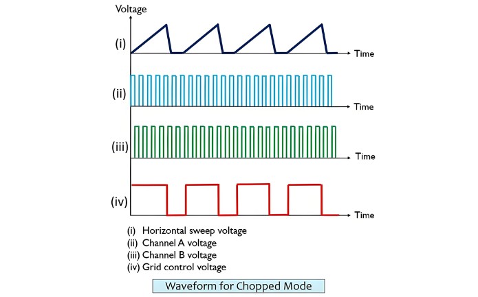
In chopped mode, the electronic switch rapidly alternates between the two channels multiple times during a single sweep. The switching is so fast that even tiny segments of each signal are displayed, creating the illusion of continuous traces for both channels.The waveform display in chopped mode is shown in the figure below:

Measurement...jpg

In chopped mode, the electronic switch operates in a free-running state at a high frequency (typically 100 kHz to 500 kHz), independent of the sweep generator’s frequency. This rapid switching ensures small segments of signals from both channels are continuously fed to the amplifier.

When the chopping rate exceeds the horizontal sweep rate, the chopped segments merge seamlessly on the CRT screen, reconstructing the original waveforms of channels A and B. Conversely, if the chopping rate is lower than the sweep rate, the display will show discontinuities—making alternate mode more suitable in such cases.Dual-trace oscilloscopes allow users to select the desired operating mode via a front-panel control.


Encyclopedia

The Electricity Encyclopedia is dedicated to accelerating the dissemination and application of electricity knowledge and adding impetus to the development and innovation of the electricity industry.

What is Voltage Stability in Power Systems?
Definition of Voltage StabilityVoltage stability in a power system is defined as the ability to maintain acceptable voltages at all buses under both normal operating conditions and after being subjected to a disturbance. In normal operation, the system’s voltages remain stable; however, when a fault or disturbance occurs, voltage instability may arise, leading to a progressive and uncontrollable voltage decline. Voltage stability is sometimes referred to as "load stability."Voltage instability c
Encyclopedia
07/26/2025
What is Cathode Ray Oscilloscope (CRO)?
What is Cathode Ray Oscilloscope (CRO)?DefinitionA cathode ray oscilloscope (CRO) is an electrical instrument for measuring, analyzing and visualizing waveforms and other electronic/electrical phenomena. As a high - speed X - Y plotter, it shows an input signal against another signal or time. Capable of analyzing waveforms, transient phenomena and time - varying quantities across a wide frequency range (from very low to radio frequencies), it mainly operates on voltage. Other physical quantities
Edwiin
07/25/2025
What is Automatic Voltage Regulator?
An automatic voltage regulator is employed to regulate voltage, converting fluctuating voltages into a constant one. Voltage fluctuations mainly stem from variations in the load on the supply system. Such voltage variations can damage the equipment within the power system. These fluctuations can be mitigated by installing voltage - control equipment at various locations, such as near transformers, generators, and feeders. Multiple voltage regulators are often placed throughout the power system t
Edwiin
05/22/2025
What is Static Voltage Regulator?
Types of Static Voltage RegulatorThe static voltage regulator is superior to electromechanical regulators in respect of the accuracy of control, response, reliability and maintenance. The static voltage regulator is mainly classified into two types. They are;Servo Type Voltage RegulatorMagnetic Amplifier RegulatorThe types of static voltage regulator are described below in details;Servo Type Voltage RegulatorThe main feature of the servo type voltage regulator is the use of the amplidyne. The am
Edwiin
05/21/2025
Inquiry
Download
IEE-Business is dedicated to serving the personnel in the global power industry.
Join IEE-Business, not only can you discover power equipment and power knowledge, but also canhnd like - minded friends!