High harmonics? Your transformer may be overheating and aging fast.
This report is based on the analysis of one-day power quality monitoring data of your company's distribution system. The data shows that there is significant three-phase current harmonic distortion in the system (with a high total harmonic distortion of current, THDi). In accordance with international standards (IEC/IEEE), harmonic currents at this level have posed substantial risks to the safe, reliable, and economical operation of the power supply transformer, mainly manifested in additional heat generation, service life reduction, and even transformer damage.
1. Overview of Test Data
Monitored Parameter: Total Harmonic Distortion of Three-Phase Current (A THD[50] Avg [%] L1, L2, L3)
Monitoring Duration: 4:00 p.m. on September 8, 2025 to 8:00 a.m. on September 9, 2025 (Rwanda Time)

Data Source: FLUKE 1732 Power Logger

During the monitoring period, the total harmonic distortion of three-phase current (THDi) remained at a high level (e.g., consistently around 60%).
This harmonic level significantly exceeds the recommended good practice range (THDi < 5%) and the general allowable range (THDi < 8%) for distribution systems specified in international standards such as IEEE 519-2014 and IEC 61000-2-2.
2. Mechanism of Harmonic Current Impact on Transformers (Problem Analysis)
Transformers are designed based on pure 50Hz sinusoidal current. Harmonic currents (especially the 3rd, 5th, and 7th harmonics) cause two core issues:
Doubled Eddy Current Loss: The eddy current loss in transformer windings is proportional to the square of the current frequency. High-frequency harmonic currents lead to a sharp increase in eddy current loss, far exceeding the design value based on fundamental current.
Additional Heat Generation and Thermal Stress: The aforementioned extra losses are converted into heat, resulting in abnormal temperature rises in transformer windings and iron cores.
3. Risk Assessment Based on International Standards
In accordance with the provisions of IEC 60076-1 and IEEE Std C57.110 regarding transformer operation under non-sinusoidal current, the main risks posed by the current harmonic level to your transformer include:
Risk 1: Accelerated Insulation Aging and Severe Service Life ReductionThe service life of a transformer is directly determined by its operating temperature. The rule of thumb indicates that for every continuous 6-10°C increase in winding temperature, the insulation aging rate doubles, and the expected service life of the transformer is halved accordingly. Long-term overheating will cause the transformer insulation to become brittle, eventually leading to breakdown faults.
Risk 2: Reduced Actual Load-Carrying Capacity (Derating Required)To avoid overheating, the transformer cannot operate at its rated capacity under the current harmonic level. According to the calculation method in IEEE Std C57.110, the transformer must be derated (for example, when THDi is 12%, the derating factor may need to be 0.92 or lower). This means that a transformer with a rated capacity of 1000kVA may have an actual safe load-carrying capacity of less than 920kVA, limiting the system's capacity expansion potential.
Risk 3: Increased Transformer Field StrengthAccording to the electromotive force formula Et = 4.44 ⋅f⋅Φm (where f is frequency), harmonics generate high-frequency magnetic flux, which induces significant eddy currents in the winding conductors, leading to local hot spots and overheating. The over-frequency of harmonics acts as an "amplifier" — even if the amplitude of the harmonic magnetic flux Φmh is small, its high-frequency characteristic will amplify the induced turn-to-turn electromotive force by h times. This amplified electromotive force is applied to the winding insulation, especially the first few turns of the coil, causing local overvoltage and greatly increasing the risk of insulation breakdown.
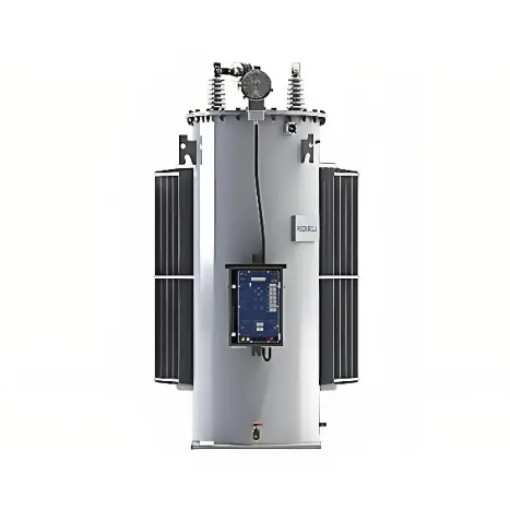
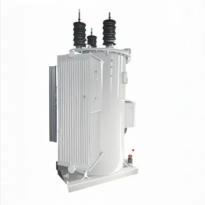
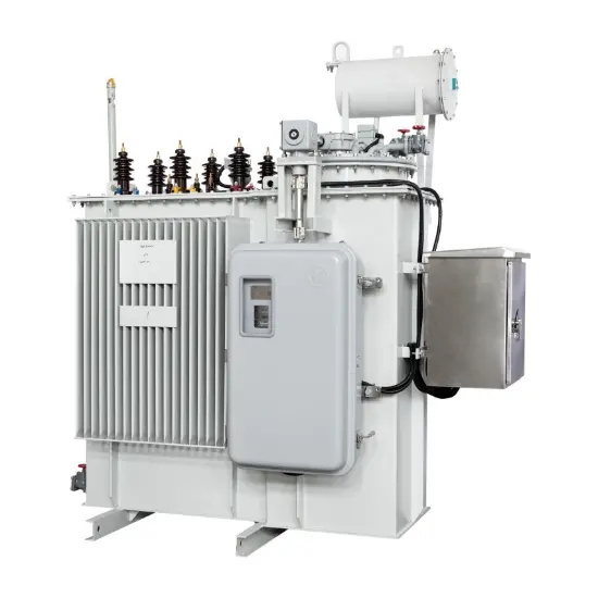
Recommended


-
11kV 15kV 22kV 33kV Fully automated, maintenance-free 32 step voltage regulator for distribution lines
-
Three Phase Automatic Step Voltage Regulator for Continuous / Step voltage regulation 13.8kV 14.4kV 19.92kV 34.5kV
-
Continuous / Step voltage regulation step voltage regulator 6kV 6.35kV 11kV 15kV 22kV 33kV – IEEE
-
6.35kV 13.2kV 14.4kV 22kV 33kV Oil-immersed self-cooled induction voltage regulator source manufacturer