1 Error Analysis of Traditional Turn Ratio Testing Methods
The QJ35 turn ratio bridge and other single-phase-phase-based testers all use the double-voltmeter principle. The QJ35, however, eliminates power supply fluctuation interference via bridge balance. For three-phase transformer ratio testing with a single power supply, corresponding terminals must be shorted and data converted, turning three-phase tests into independent single-phase measurements, with √3 Yd conversion based on connection groups.
Special transformers, with different connection modes than standard ones , face major challenges with this method. Scott transformers have primary winding electrical connections, while rectifier transformers have secondary ones. Single-phase testing with shorted magnetic circuits alters phase connections, causing significant ratio deviations. It also fails to accurately measure primary-secondary phase differences, making connection mode judgment impossible.
2 Testing Methods for Turn Ratio and Connection Mode of Special Transformers
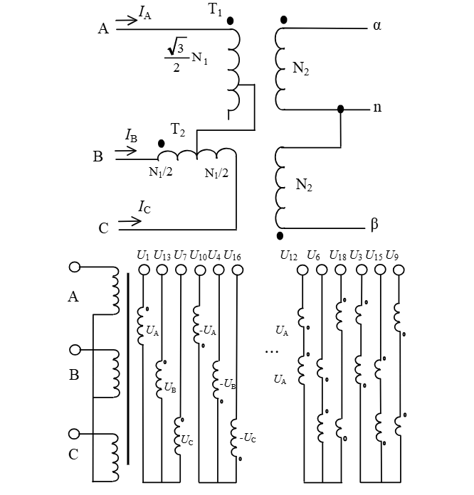
To efficiently test the turn ratio of special transformers (per prior analysis), use three-phase (120° phase difference, standard) or two-phase (90° phase difference, for inverse Scott transformers) power supply outputs. The key: test per the transformer’s actual operation, apply ~110V, measure primary-secondary voltage ratios and phase differences to determine turn ratio and connection mode.
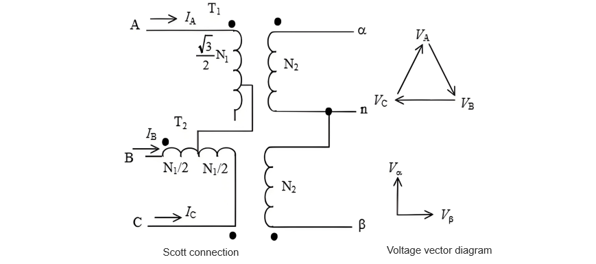
In Figure 2, (N,n) is the instrument signal ground. Apply standard three-phase voltage to the transformer’s high-voltage side, measure phase voltages (UA, UB, UC, Ua, Ub, Uc) relative to the signal ground. Use vector operations to calculate line voltages (UAB, UBC, UCA, Uab, Ubc, Uca). Derive turn ratios (KAB/ab, KBC/bc, KCA/ca) per definition, and determine groups via UAB-Uab angle differences. For inverse Scott transformers, apply 90° two-phase voltage to the high-voltage side; similarly measure turn ratios and phase differences. This method aligns the test magnetic circuit with the transformer’s working magnetic circuit, ensuring results reflect actual turn ratios and connection modes.
3 Working Principle of the Tester
With the rapid development of large - scale integrated circuits, the performance improvement of power source devices, and the in - depth evolution of digital signal processing technology, it is now basically possible to design special turn ratio testing instruments in accordance with the aforementioned ideas. The instrument can be roughly divided into three parts: power source, multi - channel signal high - speed acquisition, and digital signal processing.
To conduct a turn ratio test on a transformer with a special wiring method, a balanced three - phase power supply or a two - phase power supply with a 90° phase difference must be used. A set signal is sent out by analog devices, and after being amplified by power devices, a three - phase AC voltage is output, so as to realize the test of the special transformer under actual operating conditions. To reduce the impact of the fluctuation of the instrument power supply (AC 220 V) on the test results, the output of the standard power supply must have a relatively high stability.
Due to the involvement of a large number of vector operations, to ensure the correct connection mode and the phase angle difference between the primary and secondary sides, at least 6 channels of signals must be collected simultaneously, that is, 3 channels of voltages on the high - voltage side and 3 channels of voltages on the low - voltage side. The instrument adopts a structural design of a single - chip microcomputer combined with an FPGA. The FPGA completes the synchronous sampling and data storage of the 6 channels of signals, and the single - chip microcomputer is responsible for data processing and output.
To avoid the impact of various complex electromagnetic interferences on the test data at the test site, eliminate various interference signals other than the fundamental wave of the AC signal of the test power supply, and use the fast Fourier transform algorithm to perform digital signal processing on each channel of signals, so as to achieve the purpose of anti - interference. Using the fast Fourier transform, the vector information of each channel of signals and the phase angle difference between the primary and secondary sides can be conveniently obtained, and then the phase angle difference and connection mode can be calculated.
To avoid the error impact of the three - phase test power supply on the measurement, when the test phase voltage is 80 V, the amplitude unbalance degree of the power supply voltage should be better than ±0.04 V, and the phase unbalance degree should be better than ±0.04°.
4 Measured Results of Scott and Inverse Scott Transformers
The special transformer turn ratio tester developed according to the above ideas has been tested in a certain substation, and the measured data are shown in Table 1.
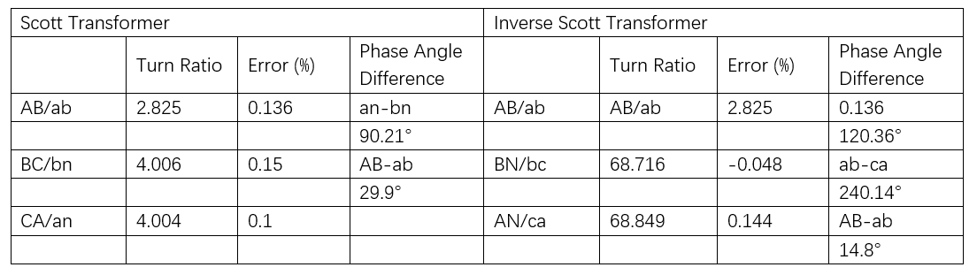
It can be seen from Table 1 that the special transformer tester based on the three - phase voltage source has successfully completed the turn ratio test of two types of special transformers, and the phase angle difference also meets the requirements of the actual transformer. The phase angle difference values in Table 1 are the phase angle differences defined in their respective columns, and an - bn represents the phase - to - phase angle difference on the low - voltage side.
5 Testing of V-v Connected Transformers
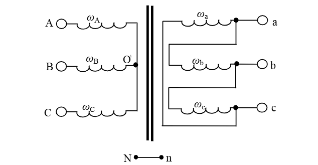
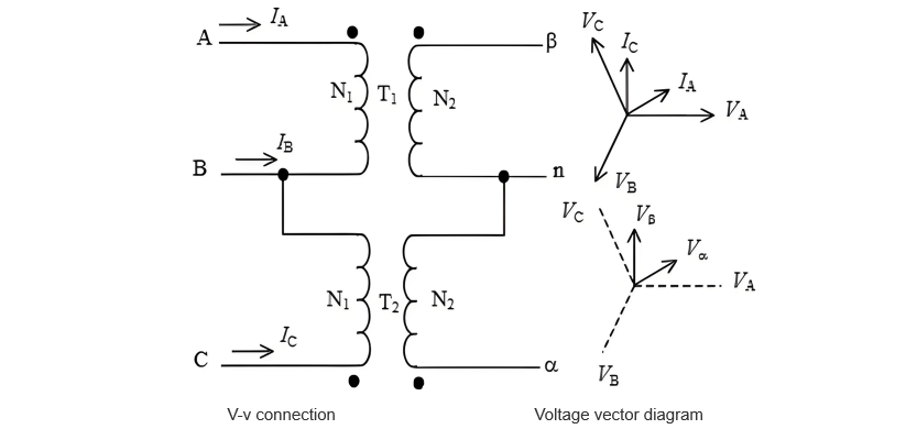
The wiring mode and voltage vector diagram of a V-v connected transformer are different from those of a Scott transformer. However, their common feature is that they convert a three-phase power supply into a two-phase power supply with a fixed phase difference to meet the requirement of unbalanced loads. Therefore, the same measurement method can be adopted. Figures 3 and 4 show the wiring diagrams and voltage vector diagrams of these two wiring modes.
Because the phase difference between the two-phase voltages on the secondary side under the V-v connection mode is 60°, instead of 90° in the Scott mode, the results given by the instrument differ when calculating the relative error of the turn ratio.
When testing with the BZJT-I tester, select the "Scott" mode and then close the switch to start the measurement.
It should be noted that the standard turn ratio here refers to the ratio of the line voltage of the three phases on the high-voltage side of the tested transformer to the voltage of the single phase on the low-voltage side Uab/Uαn or Uab/Uβn. In the structural diagram below, a and b correspond to α and β of the Scott transformer, and n in the diagram corresponds to the common terminal of the α and β phases.
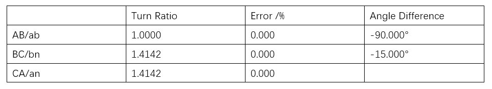
Table 2 shows the test results of a Scott transformer. When calculating the error of the "AB/ab" item, the instrument internally divides the input standard turn ratio by 1.4142 as the calculation benchmark. For the V-v connected transformer, since the phase difference between the two-phase voltages on the secondary side is 60°, a fixed difference of 41.42% is introduced into the calculation of the relative error, but the actually measured value of the turn ratio is correct.
For the V-v connected transformer, the values of the two phase angle differences should be –60.000° (phase difference of the phase voltages on the secondary side) and –300.00° (phase difference of the line voltages between the primary and secondary sides).
6 Conclusion
Using a single - phase test power supply cannot meet the measurement requirements for the turn ratio and connection mode of special transformers with complex wiring modes. To adapt to the turn ratio testing work of on - site and special transformer manufacturers, a three - phase test power supply mode should be selected for measurement. The special turn ratio tester, which is based on the output of a three - phase standard voltage source and supported by high - speed synchronous acquisition technology and digital signal processing technology, can well complete the tests of the turn ratio and connection mode.