1 Principle and Role of Electronic Current Transformers
1.1 Working Principle of ECT
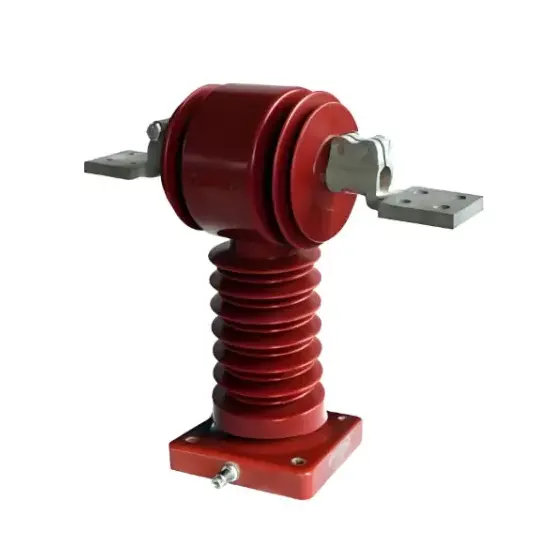
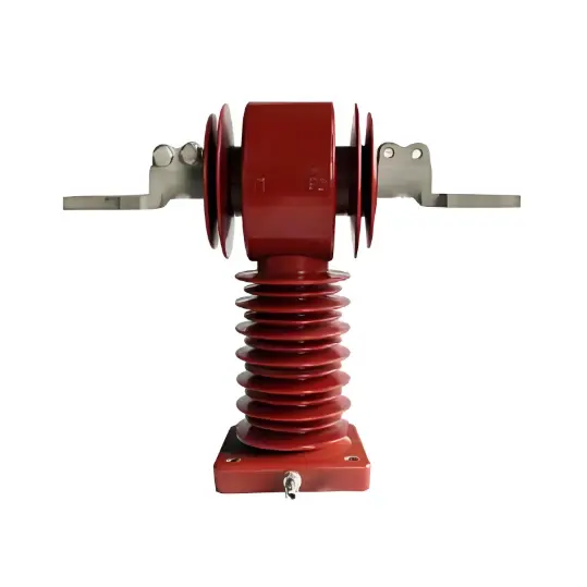
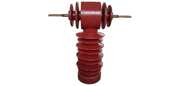
An Electronic Current Transformer (ECT) is a key device for managing safe power system operations, converting large currents into manageable small-current signals for measurement and control. Unlike traditional transformers (relying on direct magnetic field interaction between primary and secondary windings), ECTs use sensors (e.g., Hall effect sensors) to detect magnetic field changes from the primary winding. These sensors output analog signals (proportional to the primary current) for electronic circuit processing (amplification, filtering, or digitization). Modern ECTs often output digital signals for direct use by protection, metering, and control systems. ECTs outperform traditional electromagnetic transformers in accuracy, dynamic range, and response speed, while being smaller, lighter, and enabling advanced data processing/communication.
1.2 Role of ECT in Power Systems
ECTs provide high-precision current measurements critical for power system monitoring, control, and protection (e.g., preventing overloads/short circuits). They ensure equipment/personnel safety and reduce power outages. For metering/billing, ECT accuracy ensures fair electricity pricing on high-voltage/large-current lines. Accurate data also helps optimize system efficiency and stability.
1.3 Secondary Circuit Structure
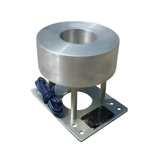
The ECT secondary circuit (core component) includes sensors (e.g., Hall effect), signal-processing circuits, analog-to-digital converters (ADCs), and communication interfaces. Components work together for accurate signal capture/transmission. Modern ECTs feature self-diagnosis for monitoring performance/faults, adapting to smarter power system demands.
2 Types of Secondary Circuit Faults in ECTs
2.1 Open-Circuit Faults
Caused by broken wires, loose joints, or aging insulation, open-circuit faults disrupt current flow, leading to abnormal (e.g., zero/low) measurements. This risks incorrect protection/control actions, endangering system safety.
2.2 Short-Circuit Faults
Occur when unintended conductor connections (e.g., insulation damage) cause sharp current spikes, risking equipment overheating/fire. They destabilize systems, potentially damaging devices or triggering protection malfunctions.
2.3 Ground Faults
Arise from improper secondary circuit grounding (e.g., insulation failure). They alter current paths, causing measurement errors, protection malfunctions, or electric shocks (hazardous for maintenance).
2.4 Overload Faults
Happen when current exceeds design capacity (e.g., due to system anomalies). Overloads cause component overheating, insulation degradation, or equipment burnout. Identified via current/temperature monitoring, they risk long-term system damage.
2.5 Electrical Noise Interference
From external/internal sources (e.g., EMI, RFI), noise distorts signals, causing measurement errors or protection system misactions (e.g., unnecessary shutdowns).
2.6 Temperature-Influenced Faults
Extreme temperatures disrupt performance: high heat degrades semiconductors/insulation (increasing short-circuit risks); low temperatures damage components. This causes measurement errors or protection failures.
2.7 Corrosion/Aging Faults
Gradual component degradation (wires, insulation) due to environmental factors (e.g., humidity, chemicals) reduces electrical performance, increasing short-circuit/ground fault risks.
3 Online Diagnosis Methods for ECT Secondary Circuit Faults
3.1 Signal Acquisition
Relies on sensors (e.g., Hall effect/current transformers) and ADCs. Hall effect sensors measure current non-invasively, ensuring safety/accuracy. ADCs convert analog signals to digital form for processing. High-speed ADCs capture subtle signal changes, enabling rapid fault detection.
3.2 Time-Domain Analysis
Involves waveform/statistical analysis. Waveform analysis checks for irregularities (e.g., asymmetry/spikes, indicating component failures). Statistical analysis (e.g., mean/standard deviation) identifies signal stability/distribution, flagging fault-induced fluctuations.
3.3 Model-Based Fault Detection
Threshold detection uses preset limits to trigger alarms for abnormal signals (based on historical data/expert knowledge). Model comparison (advanced) compares real-time data to a “healthy” system model, detecting deviations for precise fault diagnosis.
3.4 Knowledge-Based Fault Location
Fault Tree Analysis (FTA) maps fault logic to identify root causes via hierarchical sub - fault analysis. Expert systems (simulating human expertise) use rules (historical data/prior knowledge) for precise fault location, handling complex scenarios.
3.5 Thermal Imaging Monitoring
Infrared thermal imagers detect abnormal heat (e.g., from overloads/aging insulation) in ECTs. Non-invasive and real-time, they enable safe fault diagnosis without interrupting operations. Combined with other methods, they improve accuracy (addressing limitations like non-temperature-related faults).
Key Notes
ECTs offer advantages over traditional transformers but face secondary circuit faults (e.g., open/short circuits, noise). Online diagnosis (signal acquisition, time-domain analysis, model-based/knowledge-based methods, thermal imaging) ensures reliable operation, adapting to modern power system demands.