1 Vibration Monitoring and Fault Diagnosis Technology for High - Voltage Shunt Reactors
1.1 Measuring Point Layout Strategy
Vibration characteristic parameters (frequency, power, energy) of high - voltage shunt reactors are fully recorded in operation logs. For vibration analysis, focus on resolving the complexity of electric field distribution at winding ends. Quantitatively evaluate field - strength distribution under operating/lightning overvoltage and voltage gradient characteristics of longitudinal insulation at over - rated voltage. Measuring point layout must meet requirements of vibration authenticity, safety, and engineering rationality. Due to tank - top high - voltage risk, sensors are preferably placed around the tank wall. Divide the tank’s outer surface into rectangular units, set geometric centers as standard points with systematic numbering, ensuring point spacing ≤ 50 cm, balancing installation space and key - area coverage. The layout scheme should be dynamically optimized based on equipment structure, technical specs, and safety standards, enabling data traceability and risk control.
1.2 Vibration Signal Feature Extraction Method
Vibration monitoring of high - voltage shunt reactors collects vibration features via a sensing system. Experiments use two conditions: 75% rated load and mechanical - constraint removal. Equipment vibration is driven by two mechanisms: iron - core magnetostrictive effect causing lateral/longitudinal periodic deformation; alternating electromagnetic force inducing 95 Hz characteristic vibration at the iron - core - gap interface. Vibration sensitivity stems from electromagnetic - mechanical coupling. Loose cores or deformed windings cause abnormal amplitude spectra (95 Hz/150 Hz), time - domain waveforms, and principal - component coefficients. Construct a multi - dimensional feature system of amplitude, skewness, and kurtosis. Research focuses on low - frequency components below 1 kHz, building a vibration characteristic model by quantifying time - frequency laws to support fault diagnosis.
The segmented discrete power spectrum above represents a signal power spectrum, as in Formula (1).

In the formula: is the number of measurement sampling points; is the sampling rate; is the sum of the squares of the amplitudes of all frequency components between - 80 Hz and 100 Hz. Due to the complex structure of high - voltage shunt reactors, multiple nonlinear factors such as reflection and refraction occur inside. The amplitude of each harmonic component varies under different conditions.
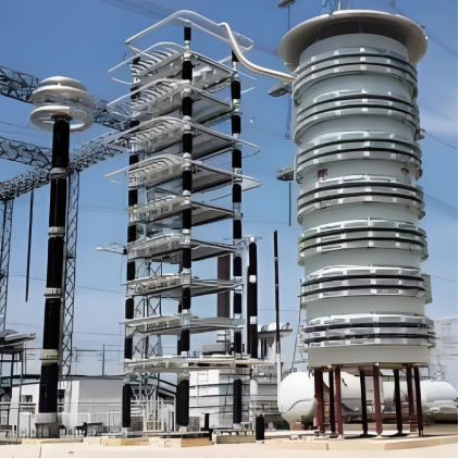
1.3 Diagnosing Internal Faults of 750 kV High - Voltage Shunt Reactors
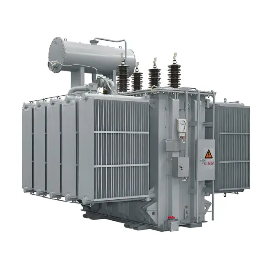
As a core reactive power compensation device in power systems, the operational reliability of high - voltage shunt reactors is directly related to system stability. These controllable reactors have a special structure and complex failure mechanisms, and faults may cause over - current/over - voltage risks. Take 750 kV devices as an example. A large - capacity turn - to - turn fault in the control winding causes a turn - number imbalance. Its harmonic components, besides DC and even - order ones, have superimposed odd - order harmonics. Also, as the induced electromotive forces in the left and right core columns of the faulty control winding differ, an unbalanced induced electromotive force is generated in the faulty - phase control winding, as shown in Formula (2).

In the formula: w is the short - circuit turn ratio of the reactor; χ is the rated voltage of the control winding. The amplitude, component coefficient, mean square deviation in the vibration signal, and the unbalanced induced electromotive force Δe in Formula (2) together constitute the internal fault characteristics of the reactor. Its fault diagnosis is shown in Formula (3).

Studies show that the correlation between vibration characteristics and the mechanical state of the reactor is stronger than that with voltage, which can effectively suppress power grid fluctuation interference. For a 750 kV reactor in normal operation, it generates balanced even - order harmonics through its three - phase structure. A single - phase fault will disrupt the harmonic balance, and due to the low - resistance characteristic of the control winding, a current five times the rated over - current will be produced. This abnormal current causes the grid - side current to surge to five times the normal level, accompanied by harmonic distortion, threatening the safety of the power grid.
2 Test Verification and Result Evaluation
2.1 Test Platform Construction
A simulation environment is built based on a two - dimensional axisymmetric electric field model, with numerical methods used to study electric field characteristics. The test system transforms reactor wires and insulation components into a 3D solid model. Via the graphical interface, it enables parameterized setting of conductor surface charge, identification of wire floating potential, and dynamic electric field visualization.
For longitudinal insulation analysis, four mixed waveform modes are adopted: full - wave/chopped - wave excitation at the winding head end, full - wave loading at the line end, and chopped - wave loading at the neutral point, simulating coil potential gradient distribution under different working conditions. In main insulation evaluation, an electro - mechanical coupling model is built for electric field concentration areas, realizing vibration characteristic calculation and fault feature extraction. The test - used model has a rated voltage of 45 kV, rated current of 630 A, and rated reactance of 1005 Ω.
2.2 Test Results and Analysis
Vibration fault tests are conducted on this paper’s method and two other methods. The test results of the three methods are compared, as shown in Table 1.
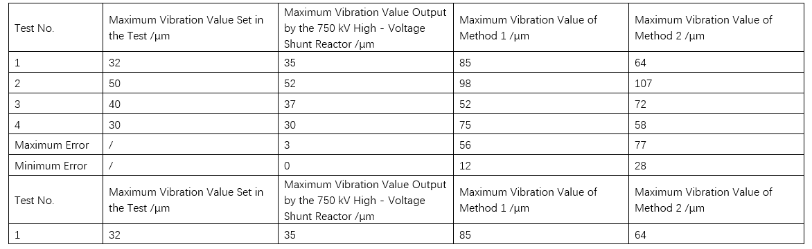
As can be seen from the data in Table 2, compared with Method 1 (maximum error of 56 μm) and Method 2 (maximum error of 77 μm), the maximum error of the 750 kV high - voltage shunt reactor vibration testing method designed in this paper is only 3 μm. In Test 6, its detected value of 30 μm is completely consistent with the set value. The maximum error of the method in this paper is reduced by more than 50 μm compared with traditional methods, and the detected value is closest to the actual value, verifying the effectiveness of the method.
The test carried out spectrum analysis on the No. 3 measuring point, and then analyzed the cause of the fault. The tested spectrum diagram of the No. 3 measuring point of the reactor is shown in Figure 1.
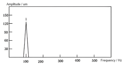
When the main magnetic circuit passes through iron cakes and air gaps, a Maxwell force field forms, with intensity twice the current, reducing magnetic field energy. Spectrum analysis shows each measuring point’s vibration frequency is ~100 Hz, and the spectrum aligns with time - domain vibration values, indicating vibration stems from the magnetostrictive effect of the main magnetic circuit insulator.
This study uses fault diagnosis accuracy as the core indicator, comparing traditional Method 1, Method 2, and this paper’s algorithm. Based on a 1000 - case test set: all three methods have benchmark accuracies >97%. This paper’s vibration testing and fault analysis method performs outstandingly, with accuracy stably >99.5% and a 99.8% peak in full - sample tests. Method 1’s accuracy peak/valley is 98.88%/98.50%, and Method 2’s accuracy range is 97.50% - 97.83%. Compared to the optimal Method 1, this method improves accuracy by 0.92 percentage points, approaching the 100.00% theoretical limit, verifying the accuracy advantage for 750 kV shunt reactor vibration testing and fault analysis.
To evaluate performance, an experiment uses fault recognition accuracy as the core indicator. Tests show detection accuracy stabilizes at 99.50% - 99.80%, confirming dual - function effectiveness: accurately measuring 750 kV reactor vibration characteristics and reliably diagnosing faults.
3 Conclusion
Research shows that when the iron core of a high - voltage shunt reactor is loose, the time - frequency characteristics of the vibration signal change regularly. Analyzing parameters such as amplitude fluctuation, variance, and the energy proportion of 200 Hz can evaluate the state. Characteristic frequency bands like 200 Hz, 300 Hz, and 500 Hz are related to working conditions. The diagnosis model has good fault identification ability. Vibration online monitoring can identify iron core loosening and winding deformation, and the tests verify the effectiveness of the method.