• Product
  • Suppliers
  • Manufacturers
  • Solutions
  • Free tools
  • Knowledges
  • Experts
  • Communities
Search


Armature Reaction in a DC Generator

Edwiin
Field: Power switch
China
Definition and Magnetic Field Effects of Armature Reaction
Definition: Armature reaction fundamentally describes the interaction between the armature magnetic field and the main field, specifically characterizing how the armature flux influences the main field flux. The armature magnetic field is generated by current-carrying armature conductors, while the main field is excited by magnetic poles. The armature flux exerts two primary effects on the main field flux:
  • Distortion of the Main Field: Armature reaction causes spatial distortion in the distribution of the main field flux;
  • Weakening of the Main Field: It simultaneously reduces the amplitude of the main field flux.

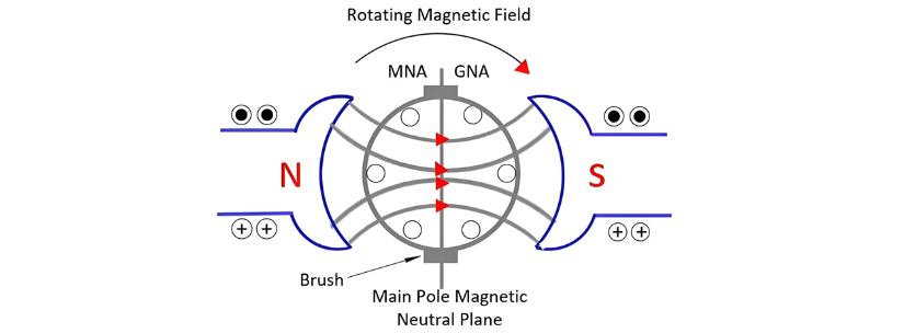
Magnetic Field Distribution in a Two-Pole DC Generator Under No-Load Condition
Consider the two-pole DC generator shown in the figure below. When the generator operates under no-load conditions (i.e., armature current is zero), only the magnetomotive force (MMF) of the main poles exists within the machine. The magnetic flux generated by the main poles' MMF is uniformly distributed along the magnetic axis, which is defined as the centerline between the north and south poles. The arrow in the figure indicates the direction of the main magnetic flux Φₘ. The magnetic neutral axis (or plane) is perpendicular to the axis of this magnetic flux.

The MNA coincides with the geometrical neutral axis (GNA). The brushes of the DC machines are always placed in this axis, and hence this axis is called the axis of commutation.

Magnetic Field Analysis of Current-Carrying Armature Conductors
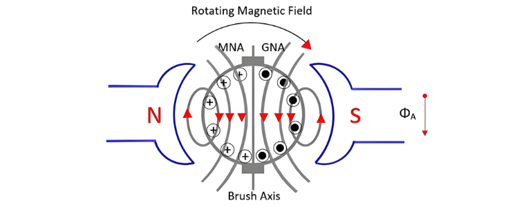
Consider a scenario where only armature conductors carry current, with no current in the main poles. The current direction is uniform for all conductors under a single pole. The direction of induced current in conductors is determined by Fleming's Right-Hand Rule, while the direction of flux generated by conductors follows the Corkscrew Rule.
Current in left-side armature conductors flows into the paper (denoted by a cross inside a circle). The magnetomotive forces (MMFs) of these conductors combine to generate a downward resultant flux through the armature. Similarly, right-side conductors carry current flowing out of the paper (denoted by a dot inside a circle), with their MMFs also combining to produce downward flux. Thus, MMFs from both sides of the conductors combine such that their resultant flux is directed downward, as indicated by the arrow for armature-conductor-induced flux Φₐ in the figure above.
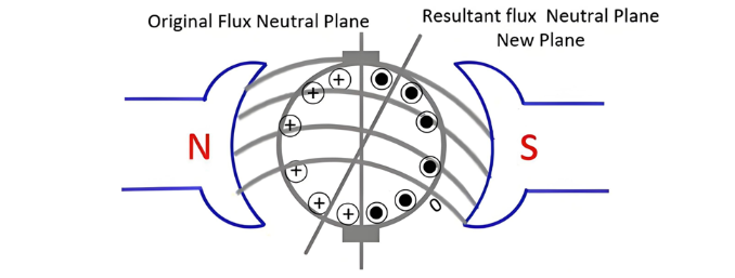
The figure below illustrates the condition where both field current and armature current act on the conductors simultaneously.

Armature Reaction Effects in Electrical Machines
Under no-load operation, the machine exhibits two magnetic fluxes: armature flux (generated by currents in armature conductors) and field pole flux (produced by main field poles). These fluxes combine to form a resultant flux Φᵣ, as illustrated in the figure above.
When field flux interacts with armature flux, distortion occurs: flux density increases at the upper tip of the N-pole and lower tip of the S-pole, while decreasing at the lower tip of the N-pole and upper tip of the S-pole. The resultant flux shifts in the direction of generator rotation, with the magnetic neutral axis (MNA)—always perpendicular to the resultant flux—moving correspondingly.
Key Effects of Armature Reaction:
  • Flux Density Asymmetry
    • Armature reaction increases flux density in one half of the pole while decreasing it in the other.
    • Total pole flux slightly decreases, reducing terminal voltage—a phenomenon called the demagnetizing effect.
  • Flux Waveform Distortion
    • The resultant flux distorts the magnetic field.
    • In generators, the MNA shifts with the resultant flux; in motors, it shifts opposite to the resultant flux.
  • Commutation Challenges
    • Armature reaction induces flux in the neutral zone, generating voltages that cause commutation issues.
  • Neutral Axis Definitions
    • The MNA is where induced EMF equals zero.
    • The geometric neutral axis (GNA) bisects the armature core symmetrically.
Give a tip and encourage the author!
Recommended
Why Regular Transformer Maintenance Matters: 5 Serious Consequences of Neglecting It
I. Allowable TemperatureWhen a transformer is in operation, its windings and iron core generate copper loss and iron loss. These losses are converted into heat energy, causing the temperature of the transformer's iron core and windings to rise. If the temperature exceeds the allowable value for a long time, the insulation will gradually lose its mechanical elasticity and age.The temperature of each part of the transformer during operation is different: the winding temperature is the highest, fol
Rockwell
09/12/2025
How to Implement Condition-Based Maintenance for Power Transformers? A Complete 4-Step Process Analysis
1. Definition of Condition-Based MaintenanceCondition-based maintenance refers to a maintenance method where decisions on whether and how to perform maintenance are determined based on the real-time operating status and health condition of equipment. It has no fixed maintenance methods or schedules. The prerequisite for condition-based maintenance is the establishment of equipment parameters and the comprehensive analysis of various operational information of the equipment, so as to make reasona
Noah
09/12/2025
Can't choose a dry-type transformer? Get expert advice – free.
Traction Rectifier TransformersRated capacity: 800 to 4400 kVA; Voltage class: 10 kV and 35 kV; Rectifier pulse number: 12-pulse and 24-pulse. Compared with 12-pulse rectifier circuits, 24-pulse rectifier circuits can reduce the harmonic pollution of the power grid by 50%, and no filtering equipment is needed at this location. It is suitable for power supply systems of urban subways and rail transit.Excitation Rectifier TransformersRated capacity: 315 to 3000 × 3 kVA; Voltage class: 10 kV, 13.8
Vziman
09/12/2025
SG10 Series Transformer Overload Protection Solution | Prevent Overheating and Damage, View Now
Operating Conditions in National Standard GB 6450-1986Ambient temperature: Maximum ambient temperature: +40°C Daily average maximum temperature: +30°C Annual average maximum temperature: +20°C Minimum temperature: -30°C (outdoor); -5°C (indoor) Horizontal axis: Product load; Vertical axis: Average coil temperature rise in Kelvin (note: not in Celsius).For Class H insulation products, the long-term temperature resistance of insulation materials is stipulated by the state as 180°C. However, the in
Rockwell
09/12/2025
Related Products
Seed Inquiry
Download
Get the IEE Business Application
Use the IEE-Business app to find equipment, obtain solutions, connect with experts, and participate in industry collaboration anytime, anywhere—fully supporting the development of your power projects and business.