Transformer on No Load Condition

Edwiin
05/28/2025

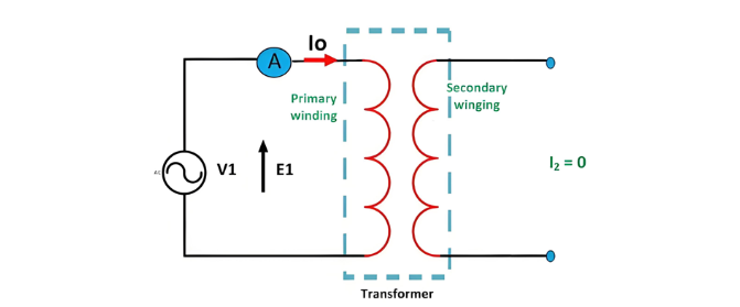
No-Load Operation of Transformer
When a transformer operates under no-load conditions, its secondary winding is open-circuited, eliminating load on the secondary side and resulting in zero secondary current. The primary winding carries a small no-load current , comprising 2 to 10% of the rated current. This current supplies iron losses (hysteresis and eddy current losses) in the core and minimal copper losses in the primary winding.
The lag angle of  is determined by transformer losses, with the power factor remaining very low—ranging from 0.1 to 0.15.
No-Load Current Components and Phasor Diagram
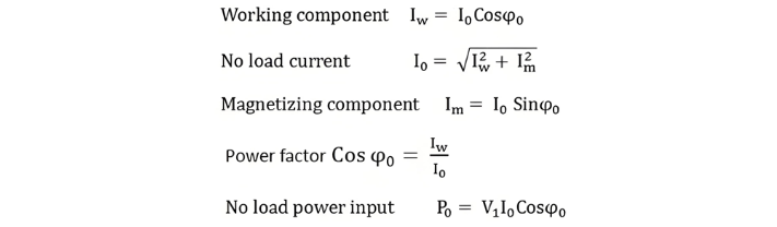
Components of No-Load Current
The no-load current I0 comprises two components:
  • Reactive (Magnetizing) Component Im
    • In quadrature with the applied voltage V1
    • Generates core flux without power consumption
  • Active (Power) Component Iw
    • In phase with V1
    • Supplies iron losses and minor primary copper losses

Phasor Diagram Construction Steps

  • The magnetizing component Im is in phase with the magnetic flux ϕ, as it generates the magnetizing flux.
  • Induced EMFs E1 and E2 in primary/secondary windings lag the flux ϕ by 90°.
  • Primary copper losses are negligible, and secondary current I2 = 0, eliminating secondary losses.
  • The no-load current I0 lags V1 by angle ϕ0 (no-load power factor angle), as depicted in the phasor diagram.
  • The applied voltage V1 is drawn equal and opposite to E1, as their no-load difference is negligible.
  • The active component Iw is aligned in phase with V1.
  • The no-load current I0 is the phasor sum of Im and Iw.

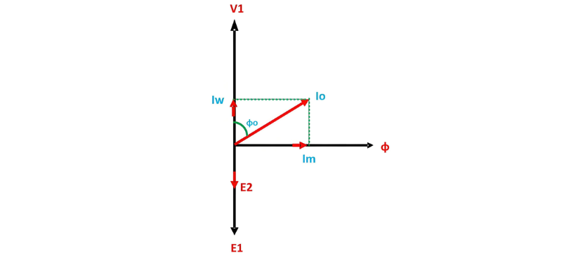
From the phasor diagram drawn above, the following conclusions are made:

Edwiin

Hello,I'm Wdwiin. A decade of hands-on experience in electrical engineering, specializing in high-voltage systems, smart grids, and renewable energy technologies. Passionate about technical exchange and knowledge sharing, committed to interpreting industry trends with professional insights to empower peers. Connection creates value—let’s explore the boundless possibilities of the electrical world together!

Cost Differences and Performance Comparison of 35kV New Energy Transformers Based on Dry-Type, Mineral Oil, and Vegetable Oil
For users, when purchasing a 35kV new energy transformer, choosing between dry-type, mineral oil-filled, or vegetable oil-filled types involves multiple considerations. These include user habits, maintenance-free performance, safety and fire resistance, volume and weight, among others. However, cost differences are undoubtedly one of the most crucial factors.To illustrate the issue intuitively, this paper selects a three-level energy efficiency dual-winding new energy transformer with a rated ca
Ron
07/26/2025
What is the connection group of a transformer?
Transformer Connection GroupThe connection group of a transformer refers to the phase difference between the primary and secondary voltages or currents. It is determined by the winding directions of the primary and secondary coils, the labeling of their start and end terminals, and the connection mode. Expressed in a clock-like format, there are 12 groups in total, numbered from 0 to 11.The DC method is commonly used to measure the transformer's connection group, mainly to verify whether the con
Vziman
07/26/2025
What is the sequence for powering down the transformer?
The sequence for shutting down a main transformer is as follows: when de-energizing, the load side should be shut down first, followed by the power supply side. For energizing operations, the reverse order applies: the power supply side is energized first, then the load side. This is because: Energizing from the power supply side to the load side makes it easier to identify the fault range and take prompt judgment and handling measures in case of a fault, preventing the fault from spreading or e
Rockwell
07/26/2025
What are the methods for switching operations of station transformers?
Let's take an auxiliary power system with two station transformers as an example. When one station transformer needs to be out of service, there are two operation methods: non-interruptive power supply and instantaneous power interruption. Generally, the method of instantaneous power interruption on the low-voltage side is preferred.The operation method for instantaneous power interruption on the low-voltage side is as follows:Open the 380V power incoming circuit breaker of the corresponding sec
Vziman
07/26/2025
Inquiry
Download
IEE-Business is dedicated to serving the personnel in the global power industry.
Join IEE-Business, not only can you discover power equipment and power knowledge, but also canhnd like - minded friends!