• Product
  • Suppliers
  • Manufacturers
  • Solutions
  • Free tools
  • Knowledges
  • Experts
  • Communities
Search


Difference Between Shunt and Series Voltage Regulator

Edwiin
Field: Power switch
China

Linear voltage regulators are mainly classified into two types: shunt voltage regulators and series voltage regulators. The key difference between them lies in the connection of the control element: in a shunt voltage regulator, the control element is connected in parallel with the load; in contrast, in a series voltage regulator, the control element is connected in series with the load. These two types of voltage regulator circuits operate on different principles and thus have their own advantages and disadvantages, which will be discussed in this article.

What is a Voltage Regulator?

A voltage regulator is a device that maintains the output voltage at a constant value despite variations in load current or input voltage. It is an essential component in electrical and electronic circuits, as it ensures that the DC output voltage remains within a specified range, unaffected by fluctuations in input voltage or load current.

Essentially, an unregulated DC supply voltage is converted into a regulated DC output voltage, where the output voltage does not exhibit significant variations. It should be noted that the control element is the core component of the circuit, and its placement differs between the two types of regulators.

Definition of Shunt Voltage Regulator

The figure below shows the shunt voltage regulator:

As is evident from the figure above, the control element is connected in parallel with the load—hence the name "shunt voltage regulator."

In this setup, the unregulated input voltage supplies current to the load, while a portion of the current flows through the control element (which is in a branch parallel to the load). This distribution helps maintain a stable voltage across the load. When the load voltage fluctuates, a sampling circuit sends a feedback signal to the comparator. The comparator then compares this feedback signal with a reference input; the resulting difference determines how much current must flow through the control element to keep the load voltage constant.

Definition of Series Voltage Regulator

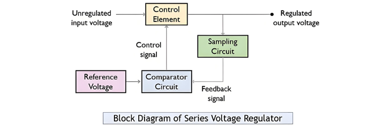
The below-given figure represents a series voltage regulator:

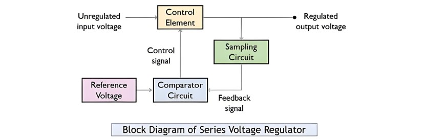
In this type of voltage regulator, the control element is connected in series with the load, hence the name "series voltage regulator."

In a series voltage regulator, the control element is responsible for regulating the portion of the input voltage that reaches the output end, acting as an intermediate regulating component between the unregulated input voltage and the output voltage. Similar to shunt regulators, a part of the output signal here is also fed back to the comparator through a sampling circuit, where the comparator compares the reference input signal with the feedback signal.

Subsequently, a control signal is generated based on the output result of the comparator and transmitted to the control element, which then regulates the load voltage accordingly.

Key Differences Between Shunt and Series Voltage Regulators

  • Connection of the Control Element:The primary distinction lies in the placement of the control element: in shunt regulators, it is connected in parallel with the load; in series regulators, it is connected in series with the load.

  • Current Flow Characteristics:In shunt regulators, only a fraction of the total current flows through the control element to maintain a stable DC output. In contrast, series regulators allow the entire load current to pass through the control element.

  • Regulation Performance:Series voltage regulators provide better regulation accuracy compared to shunt voltage regulators.

  • Compensation Mechanism:To keep the load voltage constant, shunt regulators adjust the current through the control element. Series regulators, however, modify the voltage across the control element to compensate for output voltage fluctuations.

  • Efficiency Dependence:The efficiency of shunt regulators depends on the load current, making them unsuitable for varying load conditions. Series regulators, by contrast, have efficiency that relies on the output voltage.

  • Design Complexity:Shunt voltage regulators are simpler to design than series voltage regulators.

  • Voltage Operation Range:Shunt regulators are limited to fixed-voltage operations, while series regulators are suitable for both fixed and variable voltage applications.

  • Control Element Ratings:In shunt configurations, the control element is a low-current, high-voltage component (since only a portion of the load current is diverted through it). In series configurations, the control element is a low-voltage, high-current component (as the entire load current passes through it).

Conclusion

In summary, both shunt and series voltage regulators serve the core purpose of voltage regulation, but the placement of the control element in their respective circuits results in distinct operational mechanisms. Their differences in connection, current handling, regulation performance, and application scenarios make each suitable for specific use cases, as detailed in the preceding analysis.

Give a tip and encourage the author!
Recommended
Why Regular Transformer Maintenance Matters: 5 Serious Consequences of Neglecting It
I. Allowable TemperatureWhen a transformer is in operation, its windings and iron core generate copper loss and iron loss. These losses are converted into heat energy, causing the temperature of the transformer's iron core and windings to rise. If the temperature exceeds the allowable value for a long time, the insulation will gradually lose its mechanical elasticity and age.The temperature of each part of the transformer during operation is different: the winding temperature is the highest, fol
Rockwell
09/12/2025
How to Implement Condition-Based Maintenance for Power Transformers? A Complete 4-Step Process Analysis
1. Definition of Condition-Based MaintenanceCondition-based maintenance refers to a maintenance method where decisions on whether and how to perform maintenance are determined based on the real-time operating status and health condition of equipment. It has no fixed maintenance methods or schedules. The prerequisite for condition-based maintenance is the establishment of equipment parameters and the comprehensive analysis of various operational information of the equipment, so as to make reasona
Noah
09/12/2025
Can't choose a dry-type transformer? Get expert advice – free.
Traction Rectifier TransformersRated capacity: 800 to 4400 kVA; Voltage class: 10 kV and 35 kV; Rectifier pulse number: 12-pulse and 24-pulse. Compared with 12-pulse rectifier circuits, 24-pulse rectifier circuits can reduce the harmonic pollution of the power grid by 50%, and no filtering equipment is needed at this location. It is suitable for power supply systems of urban subways and rail transit.Excitation Rectifier TransformersRated capacity: 315 to 3000 × 3 kVA; Voltage class: 10 kV, 13.8
Vziman
09/12/2025
High harmonics? Your transformer may be overheating and aging fast.
This report is based on the analysis of one-day power quality monitoring data of your company's distribution system. The data shows that there is significant three-phase current harmonic distortion in the system (with a high total harmonic distortion of current, THDi). In accordance with international standards (IEC/IEEE), harmonic currents at this level have posed substantial risks to the safe, reliable, and economical operation of the power supply transformer, mainly manifested in additional h
Leon
09/12/2025
Related Products
Seed Inquiry
Download
Get the IEE Business Application
Use the IEE-Business app to find equipment, obtain solutions, connect with experts, and participate in industry collaboration anytime, anywhere—fully supporting the development of your power projects and business.