Superheated Steam and Steam Phase Diagram

Electrical4u
03/21/2024

WechatIMG1856.jpeg

Superheated Steam

When saturated steam generated in steam boiler is further passed through a heat transfer surfaces, then its temperature will starts increasing above evaporation or saturation.
Steam is described as super heated, if its temperature is more than that of its saturation temperature. Degree of super-heat is directly related with the temperature of the steam heated above the saturation temperature.

Super heat can only be provided to saturated steam and not to steam with presence of moisture content. For achieving a super heat, saturated steam has to pass through another heat ex-changer. This heat ex-changer for super-heating is called a secondary heat ex-changer within the boiler. Hot flue gas coming out from the boiler is considered to be a best way of heating the saturated steam.

Superheated steam finds its application in steam power plants for the generation of electrical power. In steam turbines, superheated steam enters at one end and exit from the other end into the condenser (may be of water or air cooled type). The differential of the Superheated steam energy between the turbine inlet and outlet causes the turbine rotor to turn. There is a gradual reduction of the steam energy while it passing through the turbine rotor.

So it is essential to have a sufficient super-heat at the turbine inlet, so as to avoid the condensation of wet steam at the later part of the turbine rotor.

Basically steam turbine rotor has got number of stages and the steam has to pass through each stage before reaching the condenser. So if the enough superheat is not provided in the steam at the turbine inlet, then the steam may get saturated while reaching the later stages of the rotor and subsequently get wetter while passing through the each successive stage.

Wet steam at the tail end of the rotor is very dangerous as it may lead to Water Hammer and severe erosion at the last stages of the turbine blades. In order to over-come this problem it is advisable to design the inlet steam parameters of steam turbine inlet in such way that super heated steam allow to enter at the turbine inlet and the turbine exhaust are designed to match the steam parameters close to saturated conditions.

One of the major reasons for using the Super heated steam in steam turbine is appreciable improvement in the thermal efficiency of the cycle.

Heat engine efficiency can be found by using either:

Carnot Cycle efficiency: Ratio of temperature difference between inlet and outlet to inlet temperature.

Rankine cycle efficiency: Ratio of heat energy at the turbine inlet and outlet to the total heat energy taken from the steam.
2. Example of calculating the
Carnot Cycle and Rankine Cycle Efficiency.
Explained by Example:
A turbine is supplied with superheated steam at 96 bar at 490oC. The exhaust is at 0.09 bar and at 12 % wetness.
Temperature of saturated steam is : 43.7oC
Determine and Compare the Carnot Cycle and
Rankine cycle.
Procedure to determine the Carnot cycle efficiency :

Procedure to determine the Rankine cycle efficiency :
Where,

Sensible heat in condensate corresponding to exhaust pressure of 0.09 bar in KJ/Kg = 183.3
3.
enthalpy curve
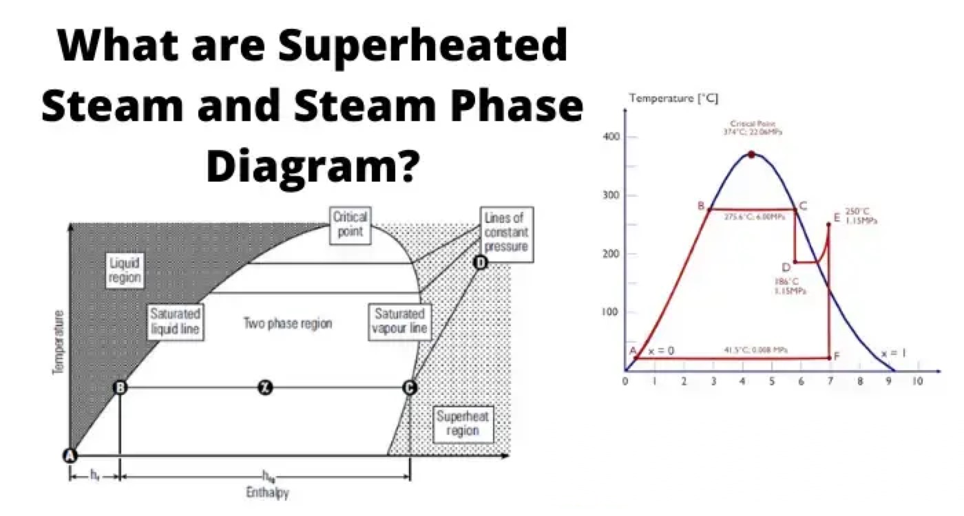
Steam-Phase diagram is a graphical representation of data provided in the steam table. Steam-Phase diagram provides the relationship between enthalpy, temperature corresponding to various pressures. Liquid Enthalpy hf. This is represented by line A-B on the phase-diagram. When the water starts receiving heat from 0o C, then it receives all its liquid entahlpy along the saturated water line A-B on the phase diagram

Enthalpy of Saturated Steam (hfg): Any further heat addition results in change in phase to saturated steam and is represented by (hfg) on phase diagram i.e B-C.

Dryness Fraction (x): When heat is applied then the liquid start changing its phase from liquid to vapour and then the dryness fraction of the mixture starts increasing i.e moving towards unity. In the phase diagram dryness fraction of the mixture is 0.5 at exactly mid of the line BC. Similarly at point c on the phase diagram dryness fraction value is 1.

Line C-D Point c is in the saturated vapour line, any further heat addition results in increasing the steam temperature i.e beginning of steam superheating represented by line C-D.
Liquid Zone → Region towards left side of the saturated liquid line
Super heat zone → Region towards right side of the saturated vapour line
Two phase Zone → Area between the saturated liquid and saturated vapour line is mixture liquid and vapour. Mixture with varied dryness fractions.
Critical Point → It is the Apex point where saturated liquid and saturated vapour lines meet. Enthalpy of evaporation diminishes to zero at critical point, it means that water changes directly to steam at critical point and thereafter.
Maximum temperature which liquid can attain or exist is equivalent to critical point.
Critical point Parameters → Temperature 374.15oC
Pressure → 221.2 bar

Values above this are super-critical values and are useful in increasing the efficiency of the rankine cycle.

Statement: Respect the original, good articles worth sharing, if there is infringement please contact delete.

Electrical4u

Electrical4U is dedicated to the teaching and sharing of all things related to electrical and electronics engineering.

What is Steady State Stability in Power System?
Definition of Steady State StabilitySteady state stability is defined as the capability of an electric power system to sustain its initial operating condition following a small disturbance, or to converge to a state closely approximating the initial condition when the disturbance persists. This concept holds critical significance in power system planning and design, the development of specialized automatic control devices, the commissioning of new system components, and the adjustment of operati
Edwiin
07/26/2025
What is Voltage Stability in Power Systems?
Definition of Voltage StabilityVoltage stability in a power system is defined as the ability to maintain acceptable voltages at all buses under both normal operating conditions and after being subjected to a disturbance. In normal operation, the system’s voltages remain stable; however, when a fault or disturbance occurs, voltage instability may arise, leading to a progressive and uncontrollable voltage decline. Voltage stability is sometimes referred to as "load stability."Voltage instability c
Encyclopedia
07/26/2025
Difference Between Shunt and Series Voltage Regulator
Linear voltage regulators are mainly classified into two types: shunt voltage regulators and series voltage regulators. The key difference between them lies in the connection of the control element: in a shunt voltage regulator, the control element is connected in parallel with the load; in contrast, in a series voltage regulator, the control element is connected in series with the load. These two types of voltage regulator circuits operate on different principles and thus have their own advanta
Edwiin
07/25/2025
What is Dual Trace Oscilloscope?
What is Dual Trace Oscilloscope?DefinitionA dual-trace oscilloscope uses a single electron beam to generate two separate traces, each deflected by an independent input source. To produce these two traces, it primarily employs two operating modes—alternate mode and chopped mode—controlled by a switch.Purpose of a Dual-Trace OscilloscopeWhen analyzing or studying multiple electronic circuits, comparing their voltage characteristics is often critical. While one could use multiple oscilloscopes for
Encyclopedia
07/25/2025
Inquiry
Download
IEE-Business is dedicated to serving the personnel in the global power industry.
Join IEE-Business, not only can you discover power equipment and power knowledge, but also canhnd like - minded friends!