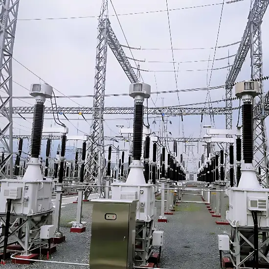
For short-circuit faults on transformer lead-out wires, bushings, and internal components, appropriate protective devices shall be installed, and shall comply with the following provisions:
Transformers with a capacity of 10 MVA or above operating individually, and transformers with a capacity of 6.3 MVA or above operating in parallel, shall be equipped with pilot differential protection. Important transformers with a capacity of 6.3 MVA or below operating individually may also be equipped with pilot differential protection.
Transformers below 10 MVA may be equipped with instantaneous overcurrent protection and overcurrent protection. For transformers of 2 MVA and above, if the sensitivity factor of the instantaneous overcurrent protection does not meet requirements, pilot differential protection is recommended.
For transformers with a capacity of 0.4 MVA and above, primary voltage of 10 kV or below, and delta-star winding connections, two-phase three-relay overcurrent protection may be used.
All protective devices specified above shall operate to trip circuit breakers on all sides of the transformer.
During transformer operation, internal faults may sometimes be difficult to detect and handle promptly, potentially leading to accidents. The installation of gas relay protection can help prevent such incidents to a certain extent.
Introduction to Gas Protection
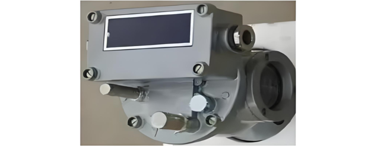
Gas protection is one of the main protections for transformers and belongs to non-electrical protection. It is divided into light gas protection and heavy gas protection. The operating principles differ: Light gas protection operates when minor internal faults cause insulation oil to decompose and generate gas due to heating. The accumulated gas in the upper part of the relay causes the open cup to lose buoyancy and sink, actuating the reed contact to close and send an alarm signal. Heavy gas protection operates when a serious internal fault causes the oil to rapidly expand due to heating or arcing, generating a large volume of gas and a high-speed oil flow toward the oil reservoir. This flow impacts the baffle inside the relay, overcoming spring resistance and moving the magnet to close the reed contact, resulting in a trip command. It should normally be set to trip mode. In addition to gas protection, non-electrical protections for large oil-immersed transformers typically include pressure relief and sudden pressure change protection.
The main difference between light and heavy gas protection lies in the relay's setting values: light gas protection only issues an alarm signal without tripping, while heavy gas protection directly initiates a trip.
The zero-sequence voltage equals the vector sum of the three-phase voltages. The calculation method for zero-sequence current is similar.
The principle of heavy gas protection is based on a float and reed relay design. The relay's oil chamber is connected to the transformer tank. When a fault generates gas, the accumulation of gas lowers the float to a certain position, closing the first-stage contact to trigger a light gas alarm. As gas continues to accumulate, the float descends further, activating the second-stage contact, closing the heavy gas circuit, and tripping the circuit breaker.
Difference in Operating Principles between Light and Heavy Gas Protection
Light gas relays consist of an open cup and reed contacts, and operate to send a signal. Heavy gas relays consist of a baffle, spring, and reed contacts, and operate to trip.
Under normal operation, the relay is filled with oil, and the open cup floats due to buoyancy, keeping the reed contacts open. When a minor internal fault occurs, the slowly rising gas enters the relay, lowering the oil level. The open cup rotates counterclockwise around its pivot, closing the reed contact and issuing an alarm signal. When a serious internal fault occurs, a large volume of gas is rapidly generated, causing a sudden increase in tank pressure and a high-speed oil flow toward the oil reservoir. This flow impacts the relay's baffle, which overcomes the spring resistance, moves the magnet toward the reed contact, closes the contact, and triggers a trip.
The relay's relay characteristic refers to the relationship between its input and output quantities throughout the entire operation process. Whether operating or returning, the relay moves directly from its initial position to its final position without stopping at any intermediate position. This "step-change" characteristic is known as the relay characteristic.