1. What Is a Distribution Transformer?
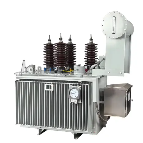
A distribution transformer is a static electrical device in a power distribution system that transfers alternating current (AC) power by transforming voltage and current levels according to the principle of electromagnetic induction.
In certain regions, power transformers with voltage ratings below 35 kV—primarily 10 kV and below—are referred to as "distribution transformers." These are typically installed at substations. In general, a distribution transformer is a static device used in distribution networks to convert AC voltage and current via electromagnetic induction for the purpose of power transmission.
Transformer products in China are generally categorized by voltage level into ultra-high voltage (750 kV and above), extra-high voltage (500 kV), 220–110 kV, and 35 kV and below. Distribution transformers typically refer to power transformers operating in distribution networks with voltage levels of 10–35 kV and capacities up to 6,300 kVA, primarily supplying power directly to end users.
2. What Is the Difference Between Distribution Transformers and Power Transformers?
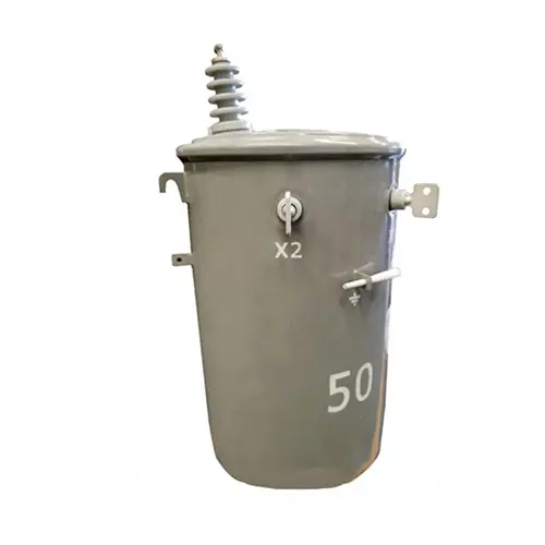
Distribution transformers are primarily used in power distribution networks to supply electricity to various end users. They typically step down high voltages to levels such as 66 kV, with low-voltage outputs of 380/220 V, 3 kV, 6 kV, or 10 kV. In contrast, power transformers are used to transfer electrical energy between power grids operating at different voltage levels. For example, a regional substation may use a transformer to exchange power between 500 kV and 220 kV grids. These transformers have large capacities and do not directly supply power to end users.
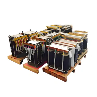
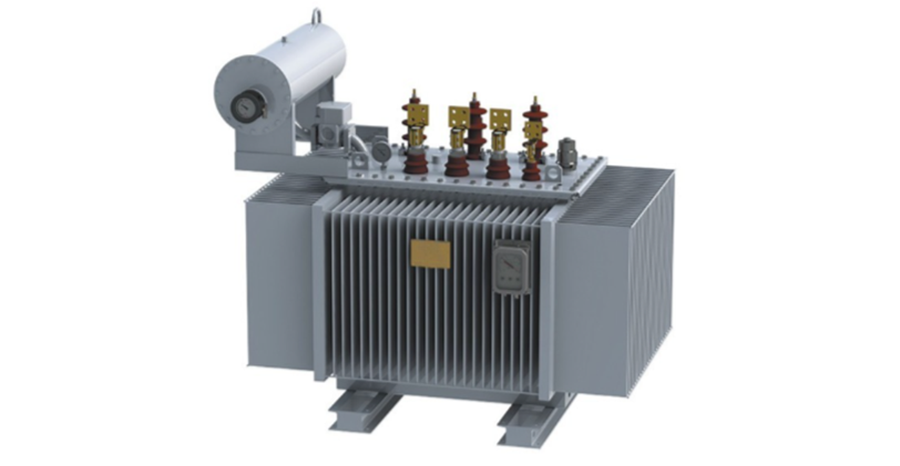
The mainstream energy-efficient distribution transformers include energy-saving oil-immersed transformers and amorphous alloy transformers. Oil-immersed distribution transformers are classified into S9, S11, and S13 series based on their loss characteristics. Compared to the S9 series, the S11 series reduces no-load losses by 20%, while the S13 series further reduces no-load losses by 25% compared to the S11 series.
As China's "energy conservation and consumption reduction" policy deepens, the state actively promotes the development of energy-efficient, low-noise, and intelligent distribution transformer products. High-energy-consuming transformers currently in operation no longer align with industry trends and face technological upgrading or replacement. In the future, they will be gradually phased out and replaced by transformers that are energy-efficient, material-saving, environmentally friendly, and low-noise.
The State Grid Corporation of China has widely adopted S11 series distribution transformers and is progressively promoting the S13 series in urban network upgrades. In the future, S11 and S13 series oil-immersed distribution transformers are expected to completely replace the existing S9 series in operation. Amorphous alloy transformers combine energy efficiency with economic performance. Their most notable feature is extremely low no-load losses—approximately 20% of those in S9 series oil-immersed transformers.
These transformers comply with national industrial policies and power grid energy conservation requirements, offering excellent energy-saving performance. They are particularly suitable for rural power grids and other areas with low load factors.
Currently, amorphous alloy transformers account for only 7%–8% of distribution transformers in operation. Only regions such as Shanghai, Jiangsu, and Zhejiang have adopted them on a large scale. Competition in the distribution transformer market is intense. High raw material costs, coupled with shortcomings in energy-efficiency evaluation systems and market supervision, along with the high initial investment required for energy-saving transformers, present challenges to their widespread adoption.