• Product
  • Suppliers
  • Manufacturers
  • Solutions
  • Free tools
  • Knowledges
  • Experts
  • Communities
Search


Analog vs Digital Multimeter | Display, Accuracy & Working Principle Differences

Edwiin
Field: Power switch
China

We know that multimeters are essential electronic test instruments used to measure various electrical quantities such as voltage, current, and resistance. Multimeters are broadly categorized into two types: analog and digital. The key difference between analog and digital multimeters lies in how they display the measured values—analog multimeters use a moving pointer on a scale, while digital multimeters show readings numerically using digits. In this discussion, we will explore further distinctions between these two types.

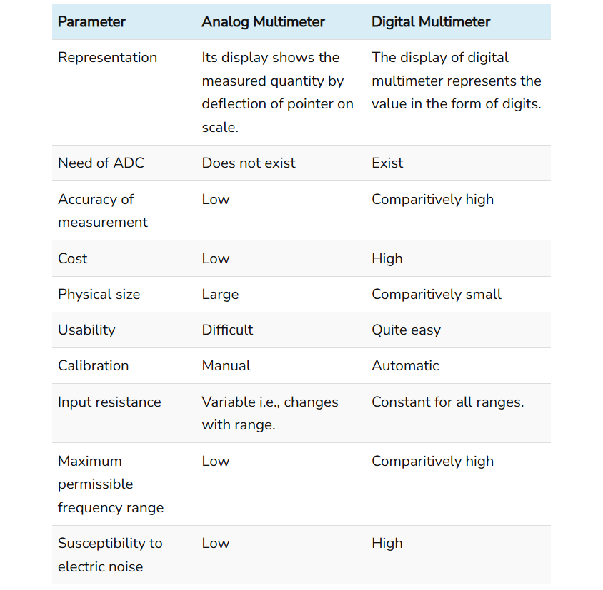
Comparison Chart

Definition of Analog Multimeter

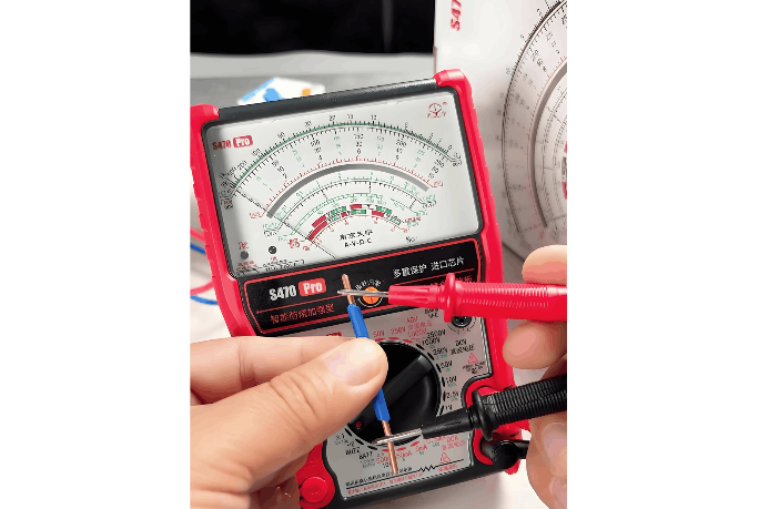
An analog multimeter is a type of multimeter that uses a needle or pointer moving across a calibrated scale to measure electrical parameters such as voltage, current, and resistance. When a measurement is taken, the result is displayed in analog form—specifically, by the deflection of a pointer that indicates a corresponding value on the scale. The position of the pointer on the scale directly reflects the magnitude of the measured quantity.

At its core, an analog multimeter consists of a moving-coil meter (also known as a galvanometer) with a needle attached to a rotating drum. This drum is positioned between the poles of a permanent magnet, and a fine wire coil is wound around it.

The fundamental operating principle is based on electromagnetic deflection. When the current to be measured flows through the coil, it generates a magnetic field. This field interacts with the fixed magnetic field of the permanent magnet, producing a torque that causes the coil and attached drum to rotate. As a result, the pointer deflects across the scale.

The movement of the pointer is regulated by small control springs connected to the drum. These springs provide a counteracting force that increases with deflection, eventually balancing the electromagnetic torque. This equilibrium determines the final position of the pointer, which thus indicates the measured value. The scale is calibrated accordingly to allow accurate reading of voltage, current, or resistance depending on the selected function.

Definition of Digital Multimeter

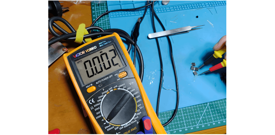
A digital multimeter (DMM) is a type of multimeter that displays measured electrical quantities numerically using a digital screen, typically an LCD or LED display. Since their introduction, digital multimeters have largely replaced analog models in many applications due to their numerous advantages, including higher accuracy, easier readability, enhanced input impedance, and additional features such as auto-ranging and data logging.

The core components of a digital multimeter include a display unit, signal conditioning circuits, an analog-to-digital converter (ADC), and encoding circuitry. The ADC plays a central role by converting the conditioned analog input signal into a digital value that can be processed and displayed.

For example, when measuring the resistance of a resistor, the DMM applies a known constant current from an internal current source through the resistor. The voltage drop across the resistor is then measured, amplified by a signal conditioning circuit, and fed into the ADC. The ADC converts this analog voltage into a digital signal, which is processed to calculate the resistance value. This result is then displayed numerically on the LCD screen, providing a clear and precise reading of the unknown resistance.

Conclusion

In summary, a multimeter—whether analog or digital—functions as a versatile, all-in-one instrument capable of performing the tasks of an ammeter, voltmeter, and ohmmeter. It can individually measure and display current, voltage, and resistance, consolidating the functionality of these three separate instruments into a single, portable device. This integration makes the multimeter an indispensable tool in electrical and electronic testing and troubleshooting.

Give a tip and encourage the author!
Recommended
Why Regular Transformer Maintenance Matters: 5 Serious Consequences of Neglecting It
I. Allowable TemperatureWhen a transformer is in operation, its windings and iron core generate copper loss and iron loss. These losses are converted into heat energy, causing the temperature of the transformer's iron core and windings to rise. If the temperature exceeds the allowable value for a long time, the insulation will gradually lose its mechanical elasticity and age.The temperature of each part of the transformer during operation is different: the winding temperature is the highest, fol
Rockwell
09/12/2025
How to Implement Condition-Based Maintenance for Power Transformers? A Complete 4-Step Process Analysis
1. Definition of Condition-Based MaintenanceCondition-based maintenance refers to a maintenance method where decisions on whether and how to perform maintenance are determined based on the real-time operating status and health condition of equipment. It has no fixed maintenance methods or schedules. The prerequisite for condition-based maintenance is the establishment of equipment parameters and the comprehensive analysis of various operational information of the equipment, so as to make reasona
Noah
09/12/2025
Can't choose a dry-type transformer? Get expert advice – free.
Traction Rectifier TransformersRated capacity: 800 to 4400 kVA; Voltage class: 10 kV and 35 kV; Rectifier pulse number: 12-pulse and 24-pulse. Compared with 12-pulse rectifier circuits, 24-pulse rectifier circuits can reduce the harmonic pollution of the power grid by 50%, and no filtering equipment is needed at this location. It is suitable for power supply systems of urban subways and rail transit.Excitation Rectifier TransformersRated capacity: 315 to 3000 × 3 kVA; Voltage class: 10 kV, 13.8
Vziman
09/12/2025
High harmonics? Your transformer may be overheating and aging fast.
This report is based on the analysis of one-day power quality monitoring data of your company's distribution system. The data shows that there is significant three-phase current harmonic distortion in the system (with a high total harmonic distortion of current, THDi). In accordance with international standards (IEC/IEEE), harmonic currents at this level have posed substantial risks to the safe, reliable, and economical operation of the power supply transformer, mainly manifested in additional h
Leon
09/12/2025
Seed Inquiry
Download
Get the IEE Business Application
Use the IEE-Business app to find equipment, obtain solutions, connect with experts, and participate in industry collaboration anytime, anywhere—fully supporting the development of your power projects and business.