What is Induction Voltage Regulators?

Edwiin
04/06/2025
What is Induction Voltage Regulators?
Types of Induction Voltage Regulators
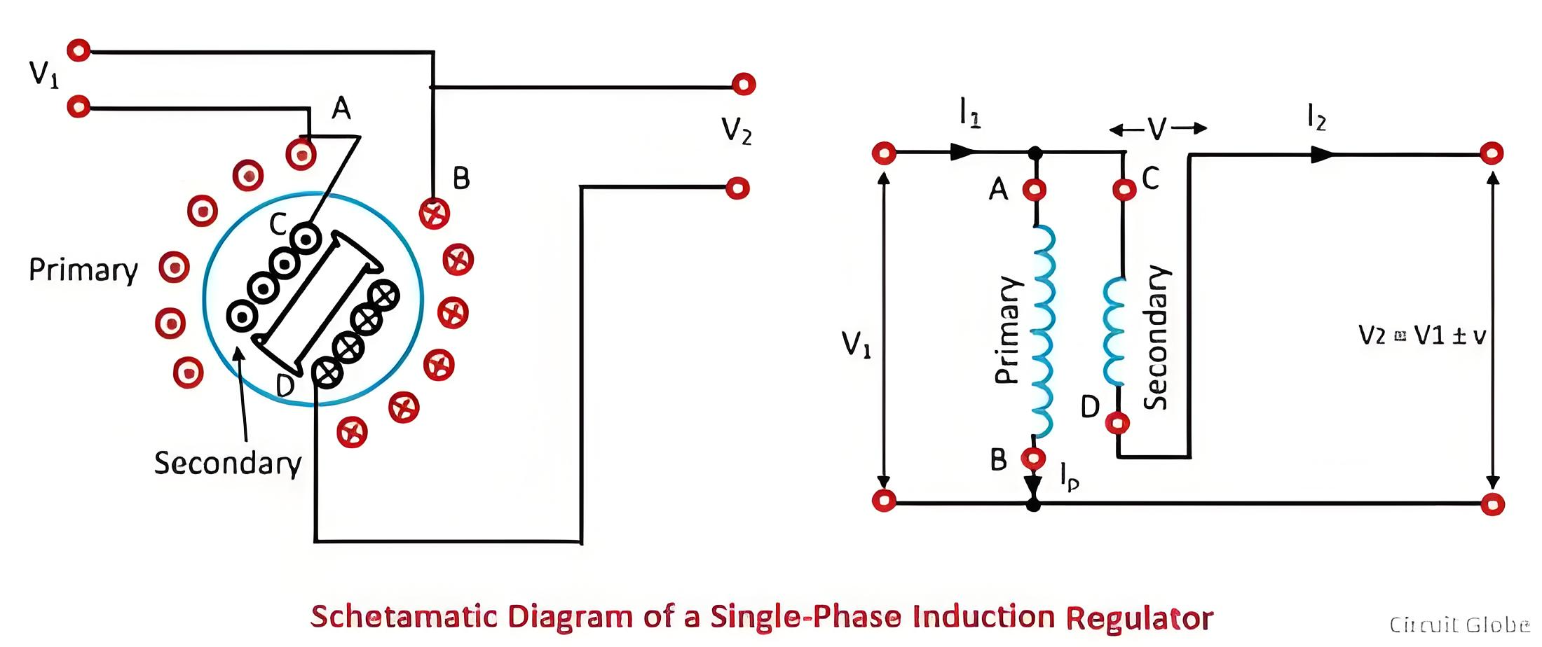
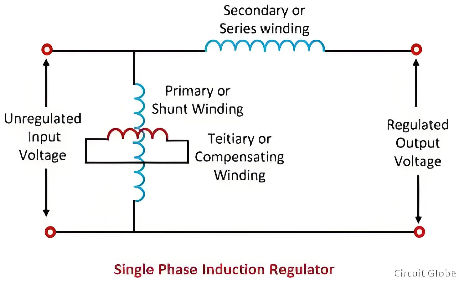
Single - phase Induction Voltage Regulator
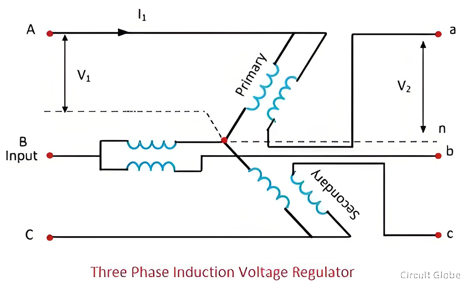
Three - Phase Induction Voltage Regulator
Topics
Hello,I'm Wdwiin. A decade of hands-on experience in electrical engineering, specializing in high-voltage systems, smart grids, and renewable energy technologies. Passionate about technical exchange and knowledge sharing, committed to interpreting industry trends with professional insights to empower peers. Connection creates value—let’s explore the boundless possibilities of the electrical world together!
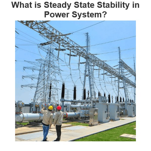
What is Steady State Stability in Power System?
Definition of Steady State StabilitySteady state stability is defined as the capability of an electric power system to sustain its initial operating condition following a small disturbance, or to converge to a state closely approximating the initial condition when the disturbance persists. This concept holds critical significance in power system planning and design, the development of specialized automatic control devices, the commissioning of new system components, and the adjustment of operati
Edwiin
07/26/2025
What is Voltage Stability in Power Systems?
Definition of Voltage StabilityVoltage stability in a power system is defined as the ability to maintain acceptable voltages at all buses under both normal operating conditions and after being subjected to a disturbance. In normal operation, the system’s voltages remain stable; however, when a fault or disturbance occurs, voltage instability may arise, leading to a progressive and uncontrollable voltage decline. Voltage stability is sometimes referred to as "load stability."Voltage instability c
Encyclopedia
07/26/2025
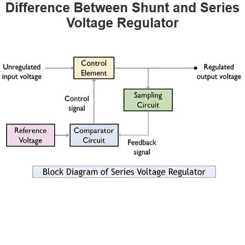
Difference Between Shunt and Series Voltage Regulator
Linear voltage regulators are mainly classified into two types: shunt voltage regulators and series voltage regulators. The key difference between them lies in the connection of the control element: in a shunt voltage regulator, the control element is connected in parallel with the load; in contrast, in a series voltage regulator, the control element is connected in series with the load. These two types of voltage regulator circuits operate on different principles and thus have their own advanta
Edwiin
07/25/2025
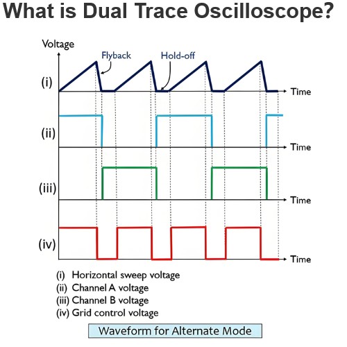
What is Dual Trace Oscilloscope?
What is Dual Trace Oscilloscope?DefinitionA dual-trace oscilloscope uses a single electron beam to generate two separate traces, each deflected by an independent input source. To produce these two traces, it primarily employs two operating modes—alternate mode and chopped mode—controlled by a switch.Purpose of a Dual-Trace OscilloscopeWhen analyzing or studying multiple electronic circuits, comparing their voltage characteristics is often critical. While one could use multiple oscilloscopes for
Encyclopedia
07/25/2025