Dielectric Gases

Electrical4u
03/25/2024

What Are Dielectric Gases

Dielectric materials are basically basic and pure electrical insulators. By applying a sensible electrical field, the dielectric gases can be polarised. Vacuum, Solids, Liquids and Gases can be a dielectric material. A dielectric gas is also called as an insulating gas. It is a dielectric material in gaseous state which can prevent electrical discharge. Dry air, Sulphur hexafluoride (SF6) etc are the examples of gaseous dielectric materials.
Gaseous dielectrics are not practically free of electrically charged particles. When a peripheral
electric field is applied to a gas, the free electrons are formed. These free electrons are accelerated from cathode to anode by the electric pressure applying a force on them.

When these electrons achieve adequate energy to bang off the electrons of the gas atoms or molecules and after that, the electrons are not involved by the molecules, and then the electron concentration will begin to build up exponentially. As a result, breakdown occurs. A few gases such as SF6 are strongly attached (the electrons are powerfully attached to the molecule), some are weakly attached for e.g., oxygen and some are not at all attached for e.g. N2. Examples of dielectric gases are Ammonia, Air, Carbon dioxide, Sulphur hexafluoride (SF6), Carbon Monoxide, Nitrogen, Hydrogen etc. The moisture content in dielectric gases may alter the properties to be a good dielectric.

Breakdown in Gases

Actually, it is the fall in resistance of the insulating gases. This will happen when the applied voltage increases than the breakdown voltage (dielectric strength). As a result of this, the gas will begin to conduct. That is, there will be a strong voltage rise in a small area in the gas. This area of strong voltage rise is the reason of partial ionisation of nearby gas and starts conduction. This is made intentionally in low pressure discharges (in an electrostatic precipitator or in fluorescent lights).

The Paschen’s law approximated the voltage which causes electrical breakdown (V = f(pd)). It is actually an equation which explains the breakdown voltage as the function of product of pressure and gap length. In that a curve is obtained, this is called Paschen’s curve. The Paschen’s curve for air and argon is represented in figure 1.
Here, as pressure is decreased, the breakdown voltage also reduced and then gradually increases which exceeds the original value. At standard pressure, the breakdown voltage reduces with the gap length up to a point.

When the gap length is reduced beyond that point, then the breakdown voltage start to increase and exceeds its original value. At high pressure and increased gap length condition, the breakdown voltage is more or less proportional to the product of the two. This is roughly proportional because of electrode effects (microscopic irregularity of electrodes may cause breakdown). The breakdown voltage of dielectric gases is also roughly proportional to density.
dielectric gases

Breakdown Mechanism

The mechanism of breakdown will directly depend on the nature of the dielectric gases and the electrode polarity in which the breakdown begins. If breakdown begins at cathode, then the supply of initiatory electrons is by the electrode itself. Then the electrons will get accelerates, numerous electrons formation occurs and it results in breakdown. If breakdown begins at anode, then the supply of initiatory electrons is by the gas itself. For e.g. air and SF6 gas. A tiny sharp point in a gas may also be the reason of breakdown of gas gap. This happens as a result of step-by-step breakdown processes. Corona formation (i.e. corona discharge) can be related to this. It is actually a short energy release (discharge) and it results in feebly ionized gas channels. When the field is too high, one of these channels will conduct.

Properties of Dielectric Gases

The preferred properties of an excellent gaseous dielectric material are as follows

  • Utmost dielectric strength.

  • Fine heat transfer.

  • Incombustible.

  • Chemical idleness against the construction material used.

  • Inertness.

  • Environmentally non poisonous.

  • Small temperature of condensation.

  • High thermal constancy.

  • Acquirable at low cost

Application of Dielectric Gases

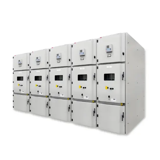
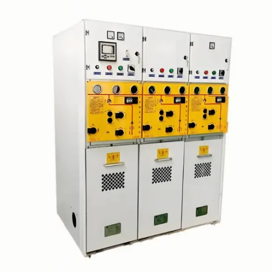
It is used in Transformer, Radar waveguides, Circuit Breakers, Switchgears, High Voltage Switching, Coolants. They are usually used in high voltage application.

Statement: Respect the original, good articles worth sharing, if there is infringement please contact delete.

Electrical4u

Electrical4U is dedicated to the teaching and sharing of all things related to electrical and electronics engineering.

What is Steady State Stability in Power System?
Definition of Steady State StabilitySteady state stability is defined as the capability of an electric power system to sustain its initial operating condition following a small disturbance, or to converge to a state closely approximating the initial condition when the disturbance persists. This concept holds critical significance in power system planning and design, the development of specialized automatic control devices, the commissioning of new system components, and the adjustment of operati
Edwiin
07/26/2025
What is Voltage Stability in Power Systems?
Definition of Voltage StabilityVoltage stability in a power system is defined as the ability to maintain acceptable voltages at all buses under both normal operating conditions and after being subjected to a disturbance. In normal operation, the system’s voltages remain stable; however, when a fault or disturbance occurs, voltage instability may arise, leading to a progressive and uncontrollable voltage decline. Voltage stability is sometimes referred to as "load stability."Voltage instability c
Encyclopedia
07/26/2025
Difference Between Shunt and Series Voltage Regulator
Linear voltage regulators are mainly classified into two types: shunt voltage regulators and series voltage regulators. The key difference between them lies in the connection of the control element: in a shunt voltage regulator, the control element is connected in parallel with the load; in contrast, in a series voltage regulator, the control element is connected in series with the load. These two types of voltage regulator circuits operate on different principles and thus have their own advanta
Edwiin
07/25/2025
What is Dual Trace Oscilloscope?
What is Dual Trace Oscilloscope?DefinitionA dual-trace oscilloscope uses a single electron beam to generate two separate traces, each deflected by an independent input source. To produce these two traces, it primarily employs two operating modes—alternate mode and chopped mode—controlled by a switch.Purpose of a Dual-Trace OscilloscopeWhen analyzing or studying multiple electronic circuits, comparing their voltage characteristics is often critical. While one could use multiple oscilloscopes for
Encyclopedia
07/25/2025
Inquiry
Download
IEE-Business is dedicated to serving the personnel in the global power industry.
Join IEE-Business, not only can you discover power equipment and power knowledge, but also canhnd like - minded friends!