Miniature Circuit Breaker [ MCB ]: What is it?

Electrical4u
03/25/2024

What Is Miniature Circuit Breaker

What is MCB?

A Miniature Circuit Breaker (MCB) is an automatically operated electrical switch used to protect low voltage electrical circuits from damage caused by excess current from an overload or short circuit. MCBs are typically rated up to a current up to 125 A, do not have adjustable trip characteristics, and can be thermal or thermal-magnetic in operation.

Fuse vs MCB

Nowadays miniature circuit breakers (MCBs) are much more commonly used in low voltage electrical networks instead of fuses. The MCB has many advantages compared to a fuse:

  1. It automatically switches off the electrical circuit during the abnormal conditions of the network (both overload and fault conditions). The MCB is much more reliable in the detection of such conditions, is it is more sensitive to change in current.

  2. As the switch operating knob comes at its off position during tripping, the faulty zone of the electrical circuit can easily be identified. But in case of a fuse, the fuse wire should be checked by opening fuse grip or cutout from fuse base, for confirming the blow of fuse wire. Thus is it much detect if an MCB has been operated compared to a fuse.

  3. Quick restoration of supply can not be possible in case of fuse, as fuses have to be rewirable or replaced for restoring the supply. But in the case of an MCB, quick restoration is possible by (literally) flipping a switch.

  4. The handling of an MCB is more electrically safe than a fuse.

  5. MCBs can be controlled remotely, whereas fuses can not.

Because of these many advantages of MCB over fuse units, in modern low voltage electrical network, the miniature circuit breaker is almost always used instead of a fuse,

The only one disadvantage of MCB over fuse is that this system is costlier than a fuse unit system.

mcb

Working Principle Miniature Circuit Breaker

There is two arrangement of operation of a miniature circuit breaker. One due to the thermal effect of over current and other due to electromagnetic effect of over current. The thermal operation of the miniature circuit breaker is achieved with a bimetallic strip whenever continuous overcurrent flows through MCB, the bimetallic strip is heated and deflects by bending.

This deflection of the bimetallic strip releases a mechanical latch. As this mechanical latch is attached to the operating mechanism, it causes to open the miniature circuit breaker contacts.

But during short circuit conditions, the sudden rising of current causes electromechanical displacement of plunger associated with tripping coil or solenoid of MCB. The plunger strikes the trip lever causing the immediate release of the latch mechanism consequently open the circuit breaker contacts. This was a simple explanation of the miniature circuit breaker working principle.

Miniature Circuit Breaker Construction

Miniature circuit breaker construction is very simple, robust and maintenance-free. Generally, an MCB is not repaired or maintained, it just replaced by a new one when required. A miniature circuit breaker has normally three main constructional parts. These are:

Frame of Miniature Circuit Breaker

The frame of a miniature circuit breaker is a molded case. This is a rigid, strong, insulated housing in which the other components are mounted.

Operating Mechanism of Miniature Circuit Breaker

The operating mechanism of a miniature circuit breaker provides the means of manual opening and closing operation of a miniature circuit breaker. It has three-positions “ON,” “OFF,” and “TRIPPED”. The external switching latch can be in the “TRIPPED” position if the MCB is tripped due to over-current.

When manually switch off the MCB, the switching latch will be in the “OFF” position. In the closed condition of an MCB, the switch is positioned at “ON”. By observing the positions of the switching latch one can determine the condition of MCB whether it is closed, tripped or manually switched off.

Trip Unit of Miniature Circuit Breaker

The trip unit is the main part, responsible for the proper working of the miniature circuit breaker. Two main types of trip mechanisms are provided in MCB. A bimetal provides protection against overload current and an electromagnet provides protection against short-circuit current.

Operation of Miniature Circuit Breaker

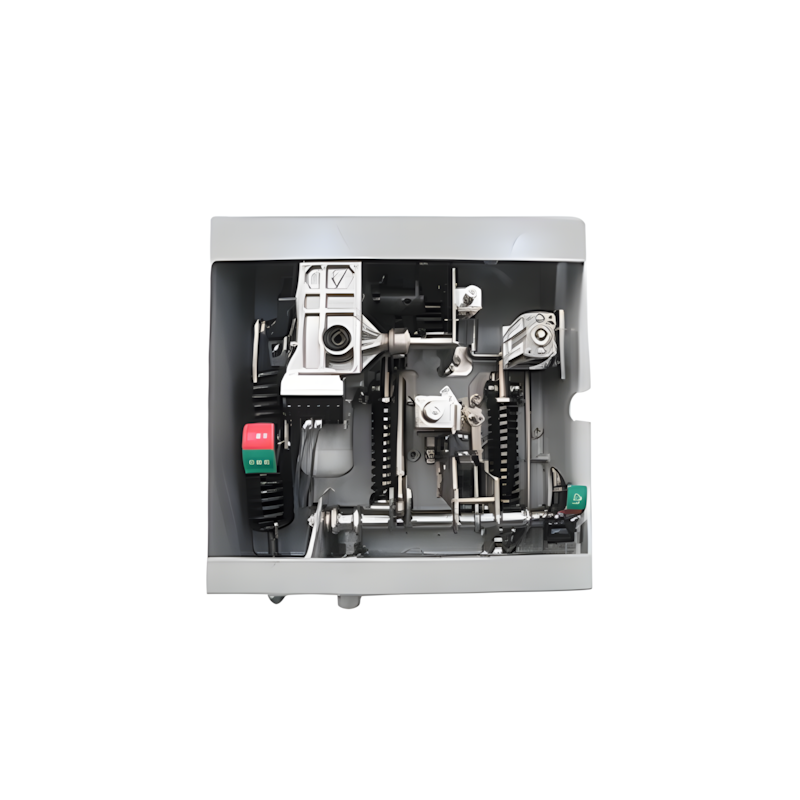
There are three mechanisms provided in a single miniature circuit breaker to make it switched off. If we carefully observe the picture beside, we will find there is mainly one bimetallic strip, one trip coil and one-hand operated on-off lever.

The electric current-carrying path of a miniature circuit breaker shown in the picture is as follows. First left-hand side power terminal – then bimetallic strip – then-current coil or trip coil – then moving contact – then fixed contact and – lastly right had side power terminal. All are arranged in series.

miniature circuit breaker

If the circuit is overloaded for a long time, the bimetallic strip becomes overheated and deformed. This deformation of bimetallic strip causes, displacement of latch point. The moving contact of the MCB is so arranged by means of spring pressure, with this latch point, that a little displacement of latch causes, release of spring and makes the moving contact to move for opening the MCB.

The current coil or trip coil is placed in such a manner, that during short circuit fault the MMF of that coil causes its plunger to hit the same latch point and make the latch to be displaced. Hence the MCB will open in the same manner.

Again when the operating lever of the miniature circuit breaker is operated by hand, that means when we make the MCB at off position manually, the same latch point is displaced as a result moving contact separated from fixed contact in the same manner.

Regardless of the operating mechanism – e.g. due to the deformation of the bimetallic strip, or due to the increased MMF of the trip coil, or due to manual operation – the same latch point is displaced and same deformed spring is released. This is ultimately responsible for the movement of the moving contact. When the moving contact separated from fixed contact, there may be a high chance of arc.

This arc then goes up through the arc runner and enters into arc splitters and is finally quenched. When we switch on an MCB, we actually reset the displaced operating latch to its previous on position and make the MCB ready for another switch off or trip operation.

Statement: Respect the original, good articles worth sharing, if there is infringement please contact delete.

Electrical4u

Electrical4U is dedicated to the teaching and sharing of all things related to electrical and electronics engineering.

What is Steady State Stability in Power System?
Definition of Steady State StabilitySteady state stability is defined as the capability of an electric power system to sustain its initial operating condition following a small disturbance, or to converge to a state closely approximating the initial condition when the disturbance persists. This concept holds critical significance in power system planning and design, the development of specialized automatic control devices, the commissioning of new system components, and the adjustment of operati
Edwiin
07/26/2025
What is Voltage Stability in Power Systems?
Definition of Voltage StabilityVoltage stability in a power system is defined as the ability to maintain acceptable voltages at all buses under both normal operating conditions and after being subjected to a disturbance. In normal operation, the system’s voltages remain stable; however, when a fault or disturbance occurs, voltage instability may arise, leading to a progressive and uncontrollable voltage decline. Voltage stability is sometimes referred to as "load stability."Voltage instability c
Encyclopedia
07/26/2025
Difference Between Shunt and Series Voltage Regulator
Linear voltage regulators are mainly classified into two types: shunt voltage regulators and series voltage regulators. The key difference between them lies in the connection of the control element: in a shunt voltage regulator, the control element is connected in parallel with the load; in contrast, in a series voltage regulator, the control element is connected in series with the load. These two types of voltage regulator circuits operate on different principles and thus have their own advanta
Edwiin
07/25/2025
What is Dual Trace Oscilloscope?
What is Dual Trace Oscilloscope?DefinitionA dual-trace oscilloscope uses a single electron beam to generate two separate traces, each deflected by an independent input source. To produce these two traces, it primarily employs two operating modes—alternate mode and chopped mode—controlled by a switch.Purpose of a Dual-Trace OscilloscopeWhen analyzing or studying multiple electronic circuits, comparing their voltage characteristics is often critical. While one could use multiple oscilloscopes for
Encyclopedia
07/25/2025
Inquiry
Download
IEE-Business is dedicated to serving the personnel in the global power industry.
Join IEE-Business, not only can you discover power equipment and power knowledge, but also canhnd like - minded friends!