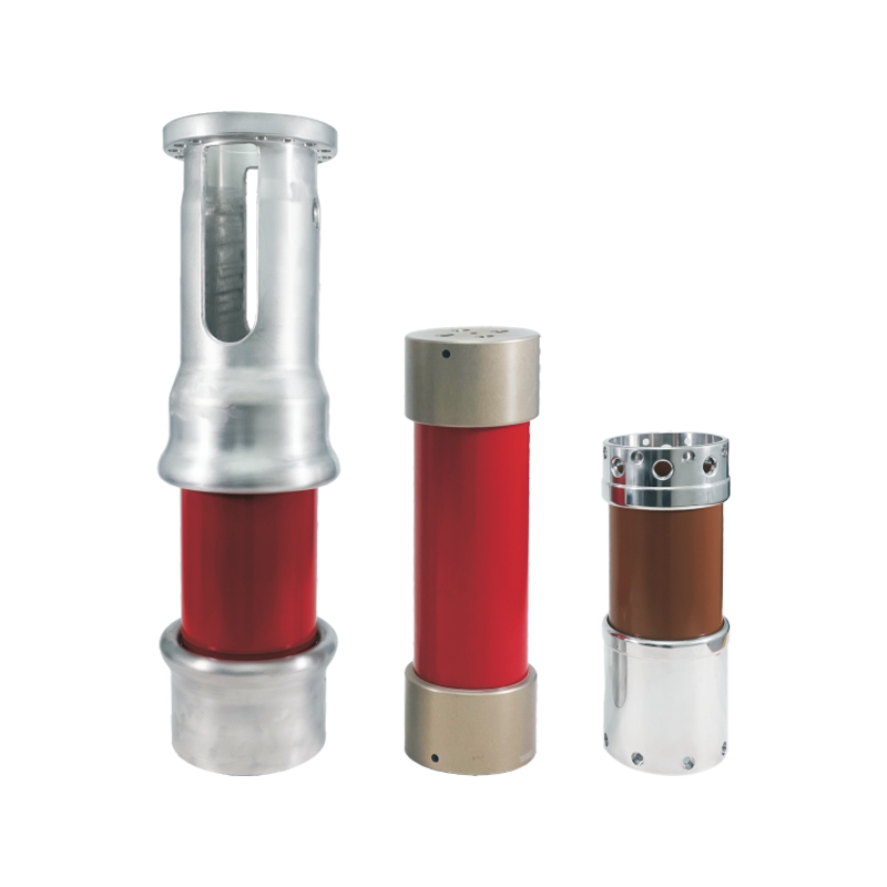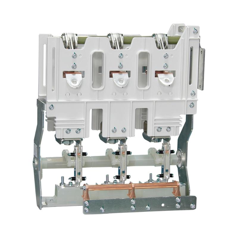
Generator circuit breakers are essentially suitable for a wide array of power generation plants, including fossil - fired, nuclear, gas turbine, combined - cycle, hydro, and pumped storage power plants. They are also ideal for retrofitting existing power stations that lack generator circuit breakers.
In the past, generator circuit breakers were commonly used in multi - unit stations where several relatively small generators were linked to a common bus. However, with the rapid growth in generator size and the escalation of system fault current levels, the interrupting capabilities of this type of switchgear were soon surpassed. Subsequently, the unit concept was adopted, where each generator had an independent steam supply auxiliary system directly connected to a step - up transformer and high - side breaker(s).
When compared to the unit connection, using generator circuit breakers to switch generators at their terminal voltage provides numerous benefits:
Streamlined Operations: It simplifies operational procedures, reducing the complexity and potential for human error during generator - related switching tasks.
Enhanced Protection: It offers improved protection for the generator, as well as for the main and unit transformers, safeguarding these critical components from electrical faults and surges.
Increased Reliability: It boosts the security of the power generation system and significantly enhances the overall availability of the power plant, minimizing downtime and maximizing power output.
Economic Gains: It also brings about economic advantages, such as reduced maintenance costs and improved long - term operational efficiency.
The key requirements for the electrical layout of power plants can be summarized as follows:
Efficient Power Transfer: Transfer the generated electrical energy from the generator to the high - voltage (HV) transmission system, taking into account operational needs, as well as factors related to availability, reliability, and economic viability.
Reliable Auxiliary Power Supply: Ensure the supply of electrical power for auxiliary and station service systems, which is crucial for maintaining safe and reliable power plant operation.
Figure 1 illustrates examples of power station layouts that utilize a generator circuit breaker to connect the generator to the main transformer, demonstrating how these breakers are integrated into the overall power plant electrical configuration.

Generator circuit breakers play a crucial and multifaceted role in power systems, fulfilling a variety of essential operation duties:
Synchronization with the HV System: They are responsible for synchronizing the generator with the system voltage at the high voltage (HV) level. This ensures a seamless connection between the generator's output and the grid, facilitating the efficient transfer of electrical energy.
Disconnection from the HV System: They enable the separation of generators from the HV system, which is particularly useful when switching off unloaded or lightly loaded generators. This operation helps in maintaining the stability and safety of the power grid.
Load Current Interruption: These breakers are capable of interrupting load currents, with the capacity to handle up to the full-load current of the generators. This functionality is vital for normal operation and load management within the power plant.
System-Fed Short-Circuit Interruption: They can interrupt system-fed short-circuits, safeguarding the generator and other components from the potentially damaging effects of excessive current flow caused by faults in the system.
Generator-Fed Short-Circuit Interruption: Similarly, they are designed to interrupt generator-fed short-circuits, protecting the generator itself from internal faults and ensuring its continued safe operation.
Out-of-Phase Current Interruption: Generator circuit breakers can handle interrupting current under out-of-phase conditions, with the ability to manage up to an out-of-phase angle of 180°. This feature is crucial for maintaining system stability during abnormal operating conditions.
Synchronization in Pumped Storage Power Plants (Motor Mode): In pumped storage power plants, when the generator-motor is started in the motor mode, the circuit breaker is used to synchronize the machine with the HV system. There are different synchronization methods available, such as using a static frequency converter (SFC) starting or back-to-back starting.
Starting Current Handling in Pumped Storage Power Plants (Motor Mode): When the generator-motor is started in the motor mode with asynchronous starting in pumped storage power plants, the circuit breaker closes on and interrupts the starting current, ensuring a smooth and controlled start-up process.
Low-Frequency Short-Circuit Current Interruption: In gas turbine, combined-cycle, and pumped storage power plants, depending on the start-up supply, the circuit breaker can interrupt generator-fed short-circuit currents at frequencies below 50/60 Hz, adapting to the specific requirements of these power generation systems.
There are multiple synchronization approaches in pumped storage power plants.
Static Frequency Converter (SFC) Starting Scheme: This scheme primarily comprises a thyristor converter connected to a unit transformer at the HV side and an inverter linked to the generator. The inverter initiates the generator's operation from a low power frequency and gradually ramps it up to the rated power frequency. Once the generator is excited to produce power, there may be a phase angle difference between its output and that of the network. At the moment when the phase difference between the generator and the HV network is minimized, the generator is synchronized with the HV network using either a generator circuit breaker or an HV circuit breaker.
Back-to-Back Starting Scheme: In a power plant with multiple generators, a back-to-back starting scheme can be employed. The power generated by a generator operating under nominal conditions is utilized to start a halted generator up to the rated power frequency. Subsequently, the generator is synchronized with the HV network using either a generator circuit breaker or an HV circuit breaker.
According to the IEC/IEEE 62271-37-13 standard, the rated short circuit duty cycle of a generator circuit breaker is specified as consisting of two units of operations, with a 30-minute interval between each operation. The duty cycle is represented as "CO – 30 minutes – CO", which means two complete short circuit interruptions, with a 30-minute gap between each short circuit closing event.This design is specifically intended to safeguard power plants and generators. Performing two consecutive close-open operations during a full short circuit could potentially cause damage to the generator and the step-up transformers.
Such types of short circuits are highly improbable, and it is also very unlikely that a plant manager would attempt to close the circuit again just 30 minutes after a full short circuit event.
The 30-minute interval between two operations is essential for restoring the initial conditions of the circuit breaker and preventing excessive heating of its components. It should be noted that this time interval may vary depending on the specific type of operation and the characteristics of the generator circuit breaker.


