How Does a Standard Breaker Respond to Electrical Fault?

Edwiin
05/15/2025

Circuit Breaker Operation for Fault Protection
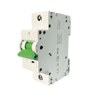
A standard circuit breaker is a critical safety device designed to interrupt electrical current during faults, such as overloads or short circuits, thereby preventing damage to the electrical system, overheating of wires, and fire hazards. Its protective action ensures the safety and reliability of the circuit.
Short Circuit Protection
  • What Happens: A short circuit occurs when a low-resistance path (e.g., direct contact between live and neutral wires) creates an abrupt surge of current far exceeding the circuit’s rating.
  • Breaker Response: The breaker detects the instantaneous spike in current and trips almost immediately (within milliseconds), cutting off the flow to:
    • Prevent excessive heat buildup from damaging components.
    • Mitigate the risk of fire or electrical arcs.

Overload Protection

  • What Happens: An overload occurs when the total current drawn by connected devices (e.g., multiple appliances or high-power equipment) exceeds the circuit’s safe capacity over time.
  • Breaker Response:
    • The breaker’s internal thermal mechanism senses the sustained excess current.
    • As the current persists, the breaker’s heating element warms up, causing a bi-metallic strip to bend gradually.
    • Once the strip bends sufficiently, the breaker trips, disconnecting the circuit to:
      • Prevent wiring from overheating and deteriorating insulation.
      • Avoid potential fire risks from prolonged overcurrent.

How a Standard Circuit Breaker Operates During Electric Faults?

A typical standard circuit breaker cannot detect ground faults or the absence of a neutral wire. Instead, it only provides protection against short circuits and overloads. This is why the National Electrical Code (NEC) requires the use of Ground Fault Circuit Interrupter (GFCI) breakers to ensure proper protection for both devices and personnel.
Below are circuit examples illustrating how a standard breaker behaves under normal and fault conditions:
Normal Condition
In the diagram below, a lighting circuit is controlled and protected by a 15-amp breaker, supplied with 120V from a 120V/240V main panel.
Since there is no fault in the circuit, all components operate normally, and the light illuminates as intended.
Short Circuit / Overload Condition
Now, consider a scenario where a short circuit or overload occurs—for example, if the hot wire comes into contact with the metallic housing of a device (such as a bulb holder). In this case, a fault current is created, traveling back to the power source through the ground wire. The ground wire is connected to the neutral wire at the main panel, forming a low-resistance path that completes the circuit.
Due to the ground wire’s extremely low resistance, a substantial current (up to 600 amps) surges through the circuit during a fault, creating a severe overload. The breaker’s internal mechanism instantly detects this excessive current and triggers a trip action. The 15-amp breaker then rapidly disconnects the circuit from the main power supply, safeguarding both the electrical device and personnel from potential hazards like overheating, arcing, or electric shock.
Fault Detection and Tripping
As illustrated in the diagram below, the 15-amp breaker trips immediately upon detecting a fault current that surpasses its rated capacity. This action disconnects the circuit from the main power supply, providing robust protection against both overloads and short circuits.
Standard Breakers and Ground Faults
As previously discussed, standard circuit breakers do not protect against ground faults—situations where electricity flows unintentionally to the ground—or broken neutral conditions, both of which pose significant safety hazards. In such scenarios:
  • Ground Fault: Current deviates from the intended circuit path and flows to the ground (e.g., through a person or faulty appliance), creating a dangerous shock risk.
  • Broken Neutral: A disconnected neutral wire can cause voltage imbalances, forcing current to seek alternative paths (e.g., through equipment casings or ground wires), which may lead to overheating or electrical shock.
In both cases, the fault current may complete the circuit through unintended routes, bypassing the standard breaker’s overload/short circuit protection mechanism. This is why specialized devices like Ground Fault Circuit Interrupters (GFCIs) or Arc Fault Circuit Interrupters (AFCIs) are required for these specific hazards.
This can lead to current flowing through unintended pathways, including neutral and ground conductors. Moreover, any exposed metal components in the circuit may become energized, potentially carrying dangerous voltages of 72V or 120V—creating a severe risk of electric shock or fire.
To address this issue, a GFCI breaker should be used instead of a standard breaker to ensure safety in the event of ground faults.
Edwiin

Hello,I'm Wdwiin. A decade of hands-on experience in electrical engineering, specializing in high-voltage systems, smart grids, and renewable energy technologies. Passionate about technical exchange and knowledge sharing, committed to interpreting industry trends with professional insights to empower peers. Connection creates value—let’s explore the boundless possibilities of the electrical world together!

What is Voltage Stability in Power Systems?
Definition of Voltage StabilityVoltage stability in a power system is defined as the ability to maintain acceptable voltages at all buses under both normal operating conditions and after being subjected to a disturbance. In normal operation, the system’s voltages remain stable; however, when a fault or disturbance occurs, voltage instability may arise, leading to a progressive and uncontrollable voltage decline. Voltage stability is sometimes referred to as "load stability."Voltage instability c
Encyclopedia
07/26/2025
What is Dual Trace Oscilloscope?
What is Dual Trace Oscilloscope?DefinitionA dual-trace oscilloscope uses a single electron beam to generate two separate traces, each deflected by an independent input source. To produce these two traces, it primarily employs two operating modes—alternate mode and chopped mode—controlled by a switch.Purpose of a Dual-Trace OscilloscopeWhen analyzing or studying multiple electronic circuits, comparing their voltage characteristics is often critical. While one could use multiple oscilloscopes for
Encyclopedia
07/25/2025
What is Cathode Ray Oscilloscope (CRO)?
What is Cathode Ray Oscilloscope (CRO)?DefinitionA cathode ray oscilloscope (CRO) is an electrical instrument for measuring, analyzing and visualizing waveforms and other electronic/electrical phenomena. As a high - speed X - Y plotter, it shows an input signal against another signal or time. Capable of analyzing waveforms, transient phenomena and time - varying quantities across a wide frequency range (from very low to radio frequencies), it mainly operates on voltage. Other physical quantities
Edwiin
07/25/2025
Analysis of the Technical Characteristics of Online Monitoring for Medium-Voltage Switchgear Status
With the increasing complexity of power system operation environment and the deepening of power system reform, traditional power grids are accelerating the transformation to smart grids. The goal of equipment condition-based maintenance is achieved through real-time perception of equipment status by new sensors, reliable communication via modern network technology, and effective monitoring by background expert systems.I. Analysis of Condition-based Maintenance StrategyCondition-based Maintenance
Oliver Watts
06/11/2025
Inquiry
Download
IEE-Business is dedicated to serving the personnel in the global power industry.
Join IEE-Business, not only can you discover power equipment and power knowledge, but also canhnd like - minded friends!