
What are the Advantages of HVDC over HVAC?
Electricity travels long distances before reaching consumers. Power plants, often remote, supply electricity through hundreds of miles and multiple substations. High-voltage transmission reduces line losses, with both AC and DC used. Though AC is familiar via utility poles and home outlets, HVDC offers unique advantages in power transmission.
The goal of power transmission is to minimize losses and costs. While both face influencing factors, HVDC has more advantages. This article explores HVDC’s advantages over HVAC:
Lower Transmission Costs
Transmission costs depend on terminal voltage conversion equipment, conductor quantity/size, tower dimensions, and losses. HVAC uses transformers for conversion—simpler and cheaper than HVDC’s thyristor-based converters, its only cost advantage.
HVAC needs at least 3 conductors for 3-phase transmission. HVDC, using earth as a return path, uses 1 conductor (monopolar) or 2 (bipolar), cutting costs. Even 3-phase conductors can carry double the power via HVDC double bipolar links.
HVAC requires larger phase-to-ground and phase-to-phase spacing, needing taller, wider towers. HVDC towers reduce installation costs.HVDC also has significantly lower transmission losses, making it more efficient.
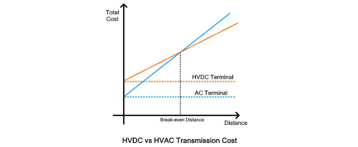
Total transmission costs can be divided into two main categories: terminal station costs and transmission line costs. The former is a fixed expense, independent of transmission distance, while the latter varies with line length. AC terminal costs are relatively low, whereas HVDC terminal costs are significantly higher. However, the cost per 100 km for HVAC transmission lines is far greater than that for HVDC lines. Thus, the total cost curves for HVAC and HVDC intersect at a point known as the break-even distance.
The break-even distance is the transmission length beyond which the total investment cost of HVAC exceeds that of HVDC. This distance varies by transmission type: approximately 400–500 miles (600–800 km) for overhead lines, 20–50 km for underwater lines, and 50–100 km for underground lines. Beyond this threshold, HVDC becomes a more efficient and economically viable choice for power transmission.
HVDC transmission incurs significantly lower losses compared to HVAC, with key improvements in the following areas:
Absence of Reactive Power Losses
HVAC transmission suffers from reactive power losses, which are directly proportional to line length, frequency, and inductive loads at the receiving end. These losses reduce effective power transfer and waste energy, limiting the maximum length of efficient HVAC lines. To mitigate this, HVAC systems rely on series and shunt compensation to reduce VARs (volt-ampere reactive) and maintain stability.
In contrast, HVDC operates without frequency or charging current, eliminating reactive power losses entirely. This removes the need for such compensation measures.
Reduced Corona Losses
When transmission voltage exceeds a critical threshold (the corona inception voltage), air molecules around conductors ionize, creating sparks (corona discharge) that waste energy. Corona losses depend on voltage level and frequency. Since DC has zero frequency, HVDC corona losses are roughly one-third of those in HVAC systems.
Absence of Skin Effect
AC current exhibits the skin effect, where current concentrates near the conductor surface, leaving the core underutilized. This uneven current distribution reduces the effective cross-sectional area of the conductor, increasing resistance (as resistance is inversely proportional to area) and resulting in higher I²R losses in HVAC lines. HVDC, with its steady direct current, avoids this effect, ensuring uniform current distribution across the conductor and minimizing resistive losses.

No Radiation or Induction Losses
HVAC transmission lines suffer from radiation and induction losses due to their constantly varying magnetic fields. Radiation losses occur because long AC lines act like antennas, radiating energy that is irrecoverable. Induction losses arise from currents induced in nearby conductors by the alternating field.In HVDC systems, the magnetic field is constant, eliminating both radiation and induction losses entirely.
Reduced Charging Current Losses
Underground and underwater cables have inherent parasitic capacitance, which requires charging before they can transmit power. Capacitance increases with cable length, and thus charging current rises proportionally.
In AC systems, cables charge and discharge multiple times per second, drawing additional current from the source to maintain this cycle. This extra current increases I²R losses in the cable.HVDC cables, however, only require charging once during initial energization or switching. This eliminates losses associated with continuous charging currents.
No Dielectric Heating Losses
The alternating electric field in AC systems affects insulation materials in transmission lines, causing them to absorb energy and convert it into heat—a phenomenon known as dielectric loss. This not only wastes energy but also shortens insulation lifespan.HVDC systems generate a constant electric field, avoiding dielectric losses and the associated insulation heating issues.
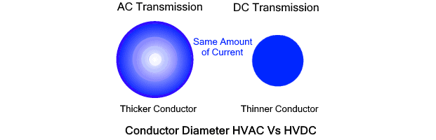
3) Thinner Conductors
The skin effect in AC causes current to concentrate near the conductor surface, requiring thicker conductors to increase surface area and accommodate higher currents.HVDC, free from the skin effect, allows current to distribute uniformly across the conductor cross-section. This enables the use of thinner conductors while maintaining the same current-carrying capacity, reducing material costs and weight.
4) Line Length Limitations
HVAC lines suffer from reactive power losses that increase directly with line length. This imposes a critical limit on HVAC transmission distance: beyond approximately 500 km for overhead lines, reactive power losses become excessively high, destabilizing the system.HVDC transmission, by contrast, has no such length restrictions, making it suitable for ultra-long-distance power delivery.
5) Reduced Cable Rating Requirements
Cables are rated for maximum tolerable voltage and current. In AC systems, peak voltage and current are roughly 1.4 times higher than their average values (which correspond to actual power delivered). However, conductors must be rated for these peak values.In DC systems, peak and average values are identical. This means HVDC can transmit the same power using cables with lower voltage and current ratings compared to HVAC. In fact, HVAC systems effectively waste about 30% of a conductor’s capacity due to their higher peak requirements.
6) Narrower Right-of-Way
"Right-of-way" refers to the land corridor required for transmission infrastructure. HVDC systems require a narrower right-of-way because they use smaller towers and fewer conductors.HVAC, by contrast, needs taller towers to support more conductors and larger insulators (rated for AC peak voltages), which demand stronger structural support. This broader footprint increases material, construction, and land costs—making HVDC superior in terms of right-of-way efficiency.
7) Superior Cable-Based Transmission
Underground and submarine cables consist of multiple conductors separated by insulation, creating parasitic capacitance between them. These cables cannot transmit power until fully charged, and capacitance (and thus charging current) increases with length.AC systems repeatedly charge and discharge cables (50–60 times per second), amplifying I²R losses and limiting cable length. HVDC cables, however, only charge once (during initial energization or switching), eliminating such losses and length restrictions.This makes HVDC the preferred choice for offshore, underwater, and underground cable transmission.

8) Bipolar Transmission
HVDC supports versatile transmission modes, with bipolar transmission being a widely used and cost-effective option. It features two parallel conductors with opposite polarities, their voltages balanced relative to the earth.If one line fails or breaks, the system seamlessly switches to monopolar mode: the remaining line continues supplying current, using the earth as the return path.
9) Controllable Power Flow
HVDC converters, based on solid-state electronics, enable precise control over power flow in AC networks. Their rapid switching capability (operating multiple times per cycle) enhances harmonic performance, dampens power swings, and optimizes the network’s power supply capacity.
10) Fast Fault Clearance
Fault currents—abnormal currents from electrical faults—pose significant risks. In HVAC systems, high fault currents can damage transmission lines, stations, generators, and loads.HVDC minimizes such risks: fault currents are lower, limiting damage to specific sections, and its fast-switching operation ensures rapid fault response, enhancing system resilience.
11) Asynchronous Grid Interconnection
HVDC enables interconnection of asynchronous AC grids with differing parameters (e.g., frequency, phase).Regions often use distinct frequencies (e.g., 50 Hz in Europe vs. 60 Hz in the U.S.), and grids may have phase differences, making direct AC interconnection impossible. HVDC, operating without frequency or phase constraints, easily links these independent systems.
12) Enabling Smart Grids
Smart grids integrate small-scale generators (solar, wind, nuclear) into a unified network with intelligent power flow control.This is feasible with HVDC, which supports asynchronous interconnection of generation units and provides full control over power distribution, aligning with smart grid requirements.
13) Reduced Noise Interference
HVDC causes far less noise interference to nearby communication lines compared to HVAC.HVAC generates audible buzzing, radio, and TV interference, with intensity tied to its frequency. HVDC, with zero frequency, produces minimal noise. Additionally, HVAC noise increases in bad weather, while HVDC noise diminishes, ensuring more stable operation.


