• Monitor For Surge Arrester
  • Monitor For Surge Arrester
Monitor For Surge Arrester
discuss personally
Model
JCQ-3E
Basic info
Brand Wone
Model NO. Monitor For Surge Arrester
Upper-limit operating current 10kA
Lower-limit operating current 50A
Series Arrester Auxiliary Equipment
Product Detail

Description:

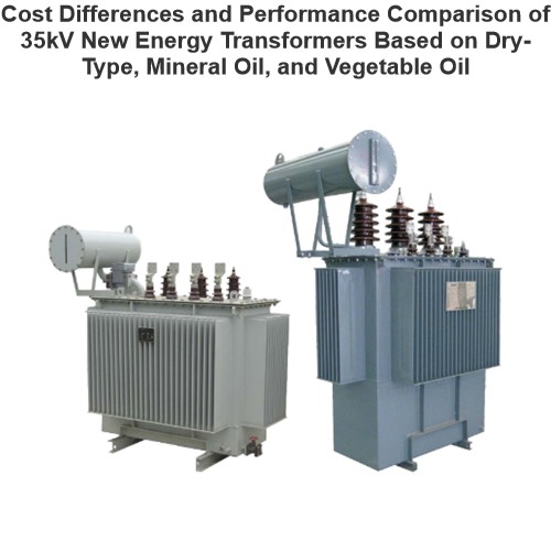
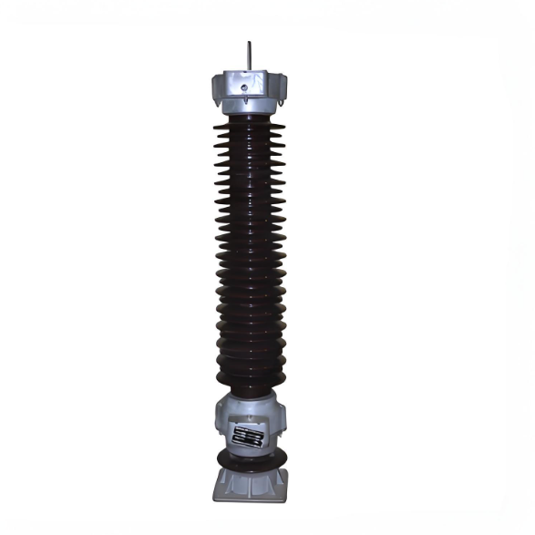
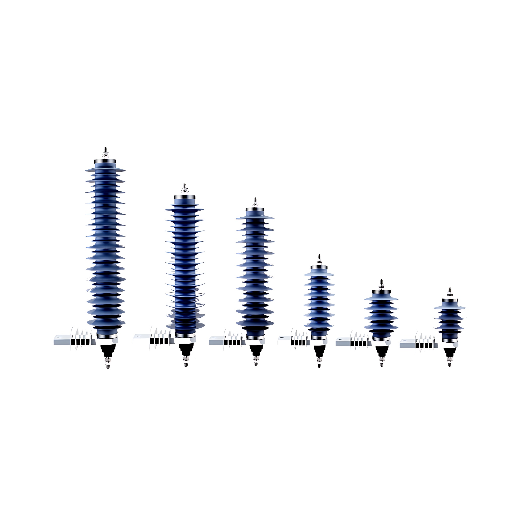
JCQ-3E Lightning arrester monitor is connected in series with the arrester below, can be used to record the number of times a lightning arrester action, but also by a leakage current monitoring device milliammeter arrester at operating voltage. Lightning arrester for 220KV and below grade, site environmental conditions with the same lightning arrester is connected, it is not suitable for a serious pollution and severe shock place; the zinc oxide valve sheet, electrical properties are greatly enhanced.

Test procedure:

First charge the condenser by turning the megger. Cut off the charge circuit when it charges steadily on the condition that you keep the megger turning. Then make the condenser which has been charged well discharge the two terminals of the coil of the counter once, so the counter counts once. You should continue to make the experiment for ten times. The counter is good if it can operate normally and reliably every time. If not, it is possible that the counter can't work or its sensitivity is lower, it needs checking or repairing.

企业微信截图_17339733931130.png

Structure and installation diagram

Conditions of using:

  • Suitable for indoor or outdoor.

  •  Environmental temperature ( -40 - +40) ℃ 

  • The attitude does not exceed 2000m.

  • The power frequency (48 - 62) Hz.

  • No severe vibration place.

Structure and properties:

 Electrical principle:

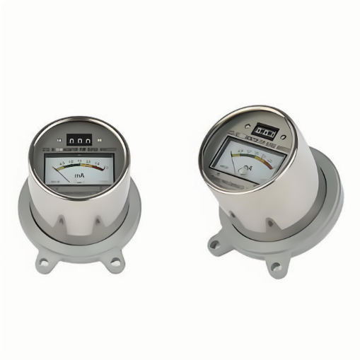
  • Lightning arrester monitor such as sampling valve plate, silicon bridge rectifier, a high-voltage capacitor, electromagnetic counter,milliammeter components. It is the use of the discharge current of the arrester, the valve plate (nonlinear resistor) the voltage generated by the silicon bridge rectifier, the charge on the capacitor, the discharge to the electromagnetic counter, every one record at a time, to achieve record lightning arrester action times.

  • This product uses the high quality stainless steel shell casing, has a good corrosion protection; the sealing performance is good, is not affected by the external environment. Internal element has good anti-aging properties, can be applicable to power system operation. JCQ-3E type lightning arrester monitor uses 2 bit digital display, the display is clear, easy to observe; is conducive to the short-term frequency by lightning arrester complete record.

The main technical performance:

image.png

Installation:

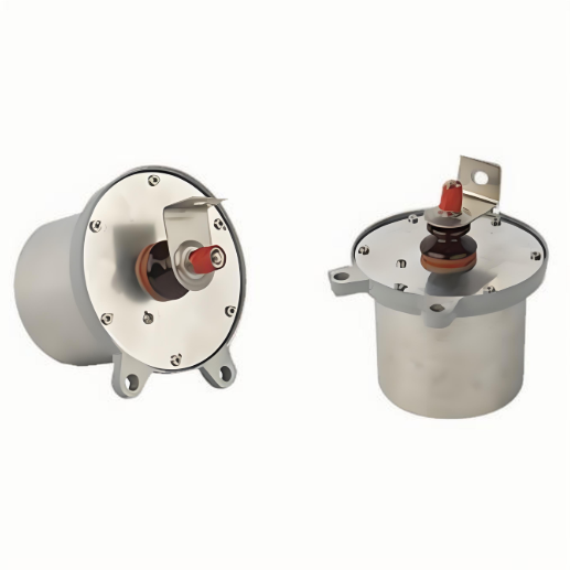
Install a counter with reference to its overall figure. The counter should be connected in series between the arrester and ground, in other words, it is connected in parallel with the flanges on the two terminals of insulating pedestal of an arrester. When you install a counter, you should scrape off the paint on the two fixture hole surface (4>11) which is on the flange of the counter first in order to en sure them being connected very well. And then fix the counter near the pedestal of an arrester by bolt of M10x40, which is a place where it is easy to be watched levelly It is also as an earthed terminal. Then connect the end of HV lead wire to the bus bar on the upper flange of insulation pedestal of an arrester by bolt of MI0x30. Check the counter after finishing installation and it mustn't be a clear incline. You must adjust it well with reference to the clause User should know that:, if the indicator of a counter does not point to “0”. Then it may be putted into operation. You shouldn't loose the M10 nut which is painted red and those six bolts of M6x20 on the pedestal in order to avoid destroying seal. The overall dimension and installation position of a counter are pointed in the following.

User should know that:

  •  User should make a simple spot experiment in one counter before its being operated and after its operating for one or two years.

  •  A simple way of testing the operation characteristic of a counter; You need one megger for 500V and one condenser for 600V 10 g F.

How does a surge arrester monitor work?

When the surge arrester is operating normally, the monitor continuously tracks its leakage current using a through-core sensor and displays the data on the corresponding interface. If an overvoltage event occurs in the system, the arrester activates to divert the resulting surge current into the ground. At this point, the current sensor in the monitor detects this change in current, triggering the counting unit to increment the operation count. The monitor then continues to track the leakage current after the arrester has operated, to determine whether the arrester has been damaged as a result of the operation.


Know your supplier
Wone
Main Categories
High Voltage Electrical Apparatus/Low Voltage Electrical Apparatus/Wire cable/Instrument meters/New energy/Tester/Production equipment/Generator/Electrical fittings/Integrated Electrical Equipment
Business Type
Design/Manufacture/Sales
Highest Annual Export (USD)
$50,000,000
Professional Experience
1 years
Workplace
65666m²m²
占位
占位
Related Products
Related Knowledges
Cost Differences and Performance Comparison of 35kV New Energy Transformers Based on Dry-Type, Mineral Oil, and Vegetable Oil
For users, when purchasing a 35kV new energy transformer, choosing between dry-type, mineral oil-filled, or vegetable oil-filled types involves multiple considerations. These include user habits, maintenance-free performance, safety and fire resistance, volume and weight, among others. However, cost differences are undoubtedly one of the most crucial factors.To illustrate the issue intuitively, this paper selects a three-level energy efficiency dual-winding new energy transformer with a rated ca
Ron
07/26/2025
What is the connection group of a transformer?
Transformer Connection GroupThe connection group of a transformer refers to the phase difference between the primary and secondary voltages or currents. It is determined by the winding directions of the primary and secondary coils, the labeling of their start and end terminals, and the connection mode. Expressed in a clock-like format, there are 12 groups in total, numbered from 0 to 11.The DC method is commonly used to measure the transformer's connection group, mainly to verify whether the con
Vziman
07/26/2025
Working Voltage in Power System
Working VoltageThe term "working voltage" refers to the maximum voltage that a device can withstand without sustaining damage or burning out, while ensuring the reliability, safety, and proper operation of both the device and associated circuits.For long-distance power transmission, the use of high voltage is advantageous. In AC systems, maintaining a load power factor as close to unity as possible is also economically necessary. Practically, heavy currents are more challenging to handle than hi
Encyclopedia
07/26/2025
What is Steady State Stability in Power System?
Definition of Steady State StabilitySteady state stability is defined as the capability of an electric power system to sustain its initial operating condition following a small disturbance, or to converge to a state closely approximating the initial condition when the disturbance persists. This concept holds critical significance in power system planning and design, the development of specialized automatic control devices, the commissioning of new system components, and the adjustment of operati
Edwiin
07/26/2025
What is the sequence for powering down the transformer?
The sequence for shutting down a main transformer is as follows: when de-energizing, the load side should be shut down first, followed by the power supply side. For energizing operations, the reverse order applies: the power supply side is energized first, then the load side. This is because: Energizing from the power supply side to the load side makes it easier to identify the fault range and take prompt judgment and handling measures in case of a fault, preventing the fault from spreading or e
Rockwell
07/26/2025
What are the methods for switching operations of station transformers?
Let's take an auxiliary power system with two station transformers as an example. When one station transformer needs to be out of service, there are two operation methods: non-interruptive power supply and instantaneous power interruption. Generally, the method of instantaneous power interruption on the low-voltage side is preferred.The operation method for instantaneous power interruption on the low-voltage side is as follows:Open the 380V power incoming circuit breaker of the corresponding sec
Vziman
07/26/2025
×
Inquiry
Download
IEE-Business is dedicated to serving the personnel in the global power industry.
Join IEE-Business, not only can you discover power equipment and power knowledge, but also canhnd like - minded friends!