| Brand | Vziman |
| Model NO. | 333kVA Single-Phase Pole-Mounted Distribution Transformer |
| Rated frequency | 50/60Hz |
| Rated capacity | 333kVA |
| Series | D |
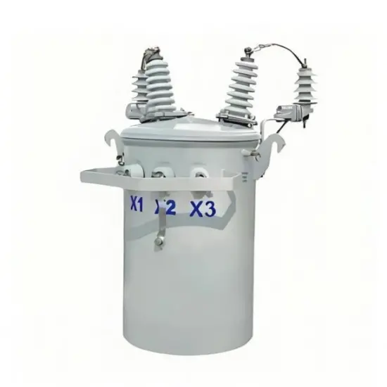
333kVA Single-Phase Pole-Mounted Distribution Transformer Description
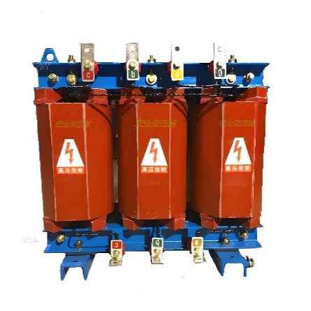
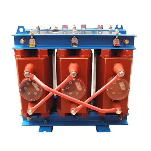
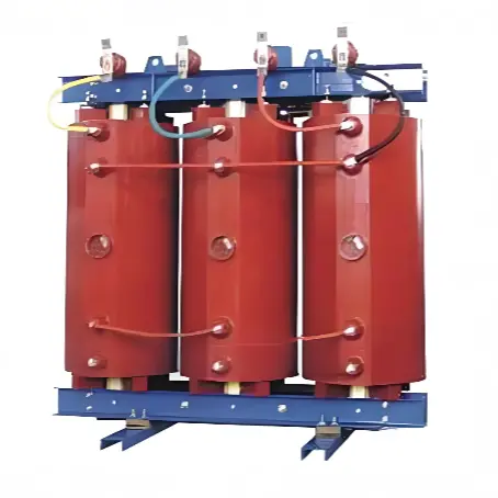
The 333kVA Single-Phase Pole-Mounted Distribution Transformer Description is a high-performance power distribution solution designed for efficiency, durability, and versatility. Built with premium copper windings and an EE-shaped core, it ensures low energy loss and reliable operation in various electrical applications.
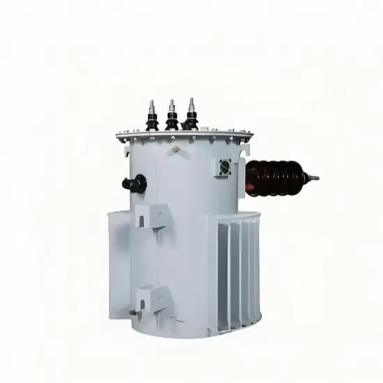
This transformer supports both 50Hz and 60Hz frequencies, making it suitable for global power systems. It is pole-mounted, saving installation space while delivering stable performance for single-phase, distribution, rectifier, and combined transformer setups.
Certified under ISO9001, CCC, and backed by a Type Test Report, it meets stringent quality and safety standards. Ideal for industrial and commercial use, the D11-333KVA combines advanced engineering with cost-effective power management, ensuring long-term reliability.
333kVA Single-Phase Pole-Mounted Distribution Transformer Features
333kVA capacity:Robust power handling
Copper windings:Enhanced conductivity & efficiency
Low-loss design :Energy-saving operation
Pole-mounted:Space-efficient installation
50Hz/60Hz compatible:Global adaptability
ISO9001 & CCC certified:Trusted quality assurance
30-day delivery:Fast and reliable supply
333kVA Single-Phase Pole-Mounted Distribution Transformer Parameter
| Rated capacity (kVA) | 333kVA |
| Input voltage (kV) | 333kVA |
| Output voltage(V) | 480-240V |
| Frequency(Hz) | 60Hz |
| No load current(%) | 1.2% |
| Cooling mode | ONAN |
| Number of windings | 1 |
| Phase number | 1 |
| High pressure gear | +1,2x2.5% |
| Cooling medium | Mineral oil 25 |
| No load loss(W) | 650w |
| Load loss(W) | 3650w |
| Short circuit voltage(%) | 2.5% |
| Oil surface temperature rise(K) | 55 |
| Winding temperature rise(K) | 65 |
| Lightning impulse withstand voltage(kV) | HV 95 / LV / |
| Power frequency withstand voltage(kV) | HV 35 / LV 5 |
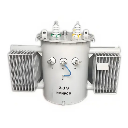
The single-phase design is more compact and lighter, making it easier to install on utility poles in areas with limited space. It is also more cost-effective for low-density, single-phase load scenarios such as rural residential areas and small commercial users, as it avoids the higher installation and maintenance costs of three-phase systems.
Q: What are the typical application scenarios for a 333kVA single-phase pole-mounted distribution transformer?
A:It is ideal for supplying power to rural villages, suburban residential communities, small retail stores, and agricultural irrigation systems. It is especially suitable for areas where three-phase power infrastructure is unavailable or where the load demand is primarily single-phase.
Q: What safety features are integrated into a 333kVA single-phase pole-mounted distribution transformer?
A:Standard safety features include a hermetically sealed tank to prevent oil leakage, pressure relief devices to handle internal overpressure, temperature monitoring sensors, and lightning arresters to protect against transient voltage surges. The pole-mounted design also includes secure mounting hardware to resist wind and vibration.