| Brand | Rw Energy |
| Model NO. | Automatic Recloser Controller |
| Rated voltage | 230V ±20% |
| Rated frequency | 50/60Hz |
| Electric energy consumption | ≤5W |
| Version | V2.3.3 |
| Series | RWK-35 |
Description
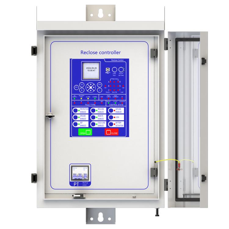
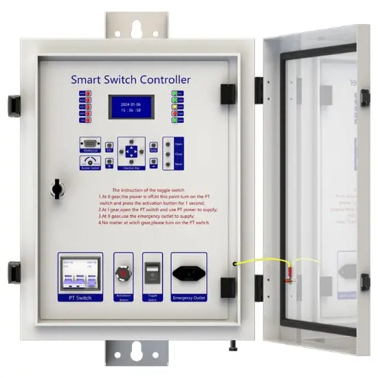
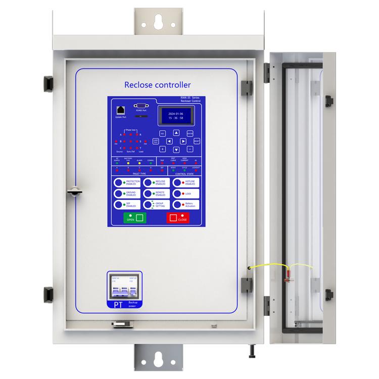
RWK-35 is an intelligent medium Voltage controller used in overhead line grid monitoring for the purpose of overhead line protection. It can be equipped with CW(VB) type vacuum circuit breaker to achieve automatic monitoring, fault analysis and store event records.
This unit offers safe line switching of faults on the power grid and provides automatic power recovery. RWK-35 series is suitable for up to 35kV outdoor switchgear include: vacuum circuit breakers, oil circuit breakers and gas circuit breakers. RWK-35 intelligent controller is equipped with line protection, control, measurement and monitoring of Voltage and current signals integrated automation and control devices outdoors.
RWK is a automatic management unit for single way/multi ways/ring network/two power sourcing, provided with all Voltage and current signals and all functions. RWK-35 column switch intelligent controller supports: Wireless (GSM/GPRS/CDMA), Ethernet mode, WIFI, optical fiber, power line carrier, RS232/485, RJ45 and other forms of communication, and can access other station premises equipment (such as TTU, FTU, DTU, etc.).
Main function introduction
1. Protection relay functions:
1) 79 Auto Reclose (Reclose) ,
2) 50P Instantaneous/Definite-Time Overcurrent (P.OC) ,
3) 51P Phase Time-Overcurrent(P.Fast curve/P.Delay curve),
4) 50/67P Directional Phase Overcurrent (P.OC-Direction mode (2-Forward /3-Reverse)),
5) 51/67P Directional Phase Time-Overcurrent (P.Fast curve/P.Delay curve-Direction mode (2-Forward/3-Reverse)),
6) 50G/N Ground Instantaneous/Definite-Time Overcurrent (G.OC),
7) 51G/N Ground Time-Overcurrent (G.Fast curve/G.Delay curve),
8) 50/67G/N Directional Ground Overcurrent (G.OC- Direction mode (2-Forward/3-Reverse)) ,
9) 51/67G/P Directional Ground Time-Overcurrent (P.Fast curve/P.Delay curve-Direction mode (2-Forward/3-Reverse)),
10) 50SEF Sensitive Earth Fault (SEF),
11) 50/67G/N Directional Sensitive Earth Fault (SEF-Direction mode (2-Forward/ 3-Reverse)) ,
12) 59/27TN Earth Fault Protection With 3RD Harmonics (SEF-Harmonic inhibit enabled) ,
13) 51C Cold Load,
14) TRSOTF Switch-Onto-Fault (SOTF) ,
15) 81 Frequency protection ,
16) 46 Negative- Sequence Overcurrent (Nega.Seq.OC),
17) 27 Under Voltage (L.Under volt),
18) 59 Over Voltage (L.Over volt),
19) 59N Zero-Sequence Over Voltage (N.Over volt),
20) 25N Synchronism-Check,
21) 25/79 Synchronism-Check/Auto Reclose,
22) 60 Voltage unbalance,
23) 32 Power direction,
24) Inrush,
25) Loss of phase,
26) Live load block,
27) High gas,
28) High temperature,
29) hotline protection.
2. Supervision functions:
1) 74T/CCS Trip & Close Circuit Supervision,
2) 60VTS. VT Supervision.
3. Control functions:
1) 86 Lockout,
2) circuit-breaker control.
4. Monitoring Functions:
1) Primary/Secondary Phases and Earth Currents,
2) Phases Current with 2nd Harmonics and Earth Current With 3RD Harmonics,
3) Direction, Primary/Secondary Line and Phase Voltages,
4) Apparent Power and Power Factor,
5) Real and Reactive Power,
6) Energy and History Energy,
7) Max Demand and Month Max Demand,
8) Positive Phase Sequence Voltage,
9) Negative Phase Sequence Voltage & Current,
10) Zero Phase Sequence Voltage,
11) Frequency, Binary Input/Output status,
12) Trip circuit healthy/failure,
13) Time and date,
14) Trip, alarm,
15) signal records, Counters,
16) Wear, Outage.
5. Communication functions:
a. Communication interface: RS485X1,RJ45X1
b. Communication protocol: IEC60870-5-101; IEC60870-5-104; DNP3.0; Modbus-RTU
c. PC software: RWK381HB-V2.1.3,The address of the information body can be edited and queried by PC software,
d. SCADA system: SCADA systems that support the four protocols shown in "b.”.
6. Data Storage functions:
1) Event Records,
2) Fault Records,
3) Measurands.
7. remote signaling remote measuring, remote controlling function can be customized address.
Technology parameters

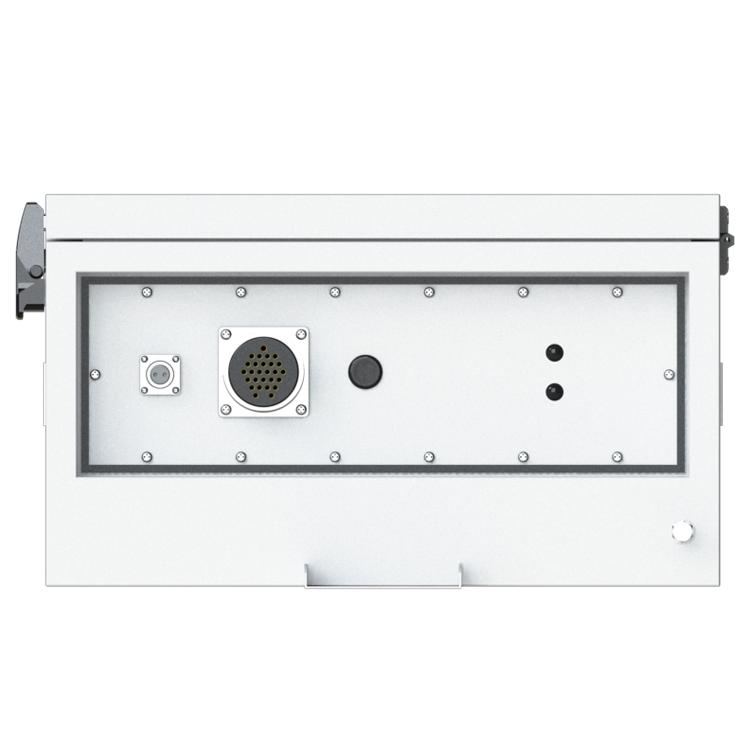
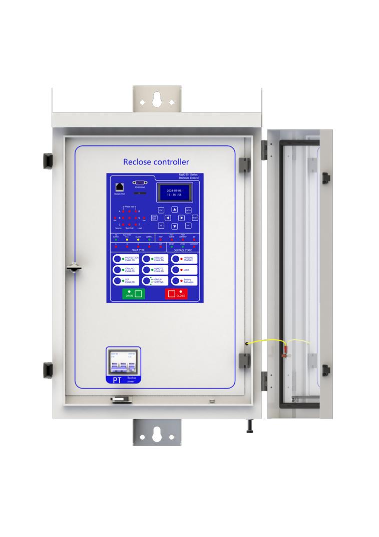
Device structure


About customization
The following optional functions are available: Power supply rated at 110V/60Hz, cabinet heating defrosting device, battery upgrade to lithium battery or other storage equipment, GPRS communication module,1~2 signal indicators,1~4 protection pressure plates, the second voltage transformer, custom aviation socket signal definition.
For detailed customization, please contact the salesman.
Q: What is a recloser?
A: The reclosing device is a device that can automatically detect the fault current, and automatically cut off the circuit when the fault occurs, and then perform multiple reclosing operations.
Q: What is the function of the recloser?
A: It is mainly used in the distribution network. When there is a temporary fault in the line (such as a branch touching the line for a short time), the reclosing device restores power supply by reclosing operation, which greatly reduces the outage time and scope and improves power supply reliability.
Q: How does the recloser determine the type of failure?
A: It monitors characteristics such as the magnitude and duration of fault currents. If the fault is permanent, after a preset number of reclosing, the reclosing device will be locked to avoid further damage to the device.
Q: What are the application scenarios of reclosers?
A: It is widely used in the urban distribution network and rural power supply network, which can effectively cope with various possible line failures and ensure the stable supply of power.


Sure, this device cannot be upgraded online, but it requires offline firmware version upgrade using a burning device to upgrade more features or fix known bugs. As this device is a customized product, you need to provide us with the device's model number and version number when upgrading. Once we have determined the upgrade plan, we will contact you and provide you with the burning device and firmware upgrade package needed for the upgrade.
Yes, this device has corresponding upper computer software (only available in windows-X86 version), which can be connected to the terminal through a serial port or network port, enabling fixed parameter configuration and viewing, address configuration for remote signaling, telemetry, and control, viewing of event reports, monitoring of electricity meters, packet capture of communication messages, and simulation of remote control functions.
Three-Section Overcurrent Protection is a coordinated protection scheme widely used in power systems to detect and isolate faults (e.g., short circuits) while ensuring selective tripping. It consists of three stages with distinct operating characteristics based on current magnitude and time delay:
Function: Responds immediately to severe overcurrents exceeding a high-set threshold (e.g., 5–10 times the rated current).
Purpose: Rapidly clears close-in faults (near the protection device) to prevent equipment damage.
Key Feature: No intentional time delay (operates in milliseconds).
Function: Triggers after a predefined short delay (e.g., 0.1–0.5 seconds) for moderate overcurrents (e.g., 2–5 times the rated current).
Purpose: Handles faults farther from the protection device, allowing downstream breakers to clear localized faults first (selectivity).
Coordination: Employs a time-graded scheme—higher fault currents (closer faults) trip faster, while lower currents (remote faults) trip slower.
Function: Activates after a longer time delay (e.g., several seconds) for low-magnitude overcurrents (e.g., 1.2–2 times the rated current).
Purpose: Serves as a backup for primary protection (Sections I/II) and addresses overloads or persistent faults.
Characteristic: May use an inverse-time curve (trip time decreases as current increases).
Coordination Principle
The three sections work hierarchically:
Section I clears severe faults instantly.
Section II handles moderate faults with short delays, prioritizing system selectivity.
Section III provides backup protection, ensuring reliability if upstream protections fail.
This layered approach minimizes outage scope, balances speed and selectivity, and enhances grid stability.
1. How to set the transformation rate
Enter the settings page: Edit → Para; Configure communication function on/off: Scroll down, find CT Rate to set current rate, find VS Rate to set voltage sensor rate, and find PT Rate to set PT rate.
2.How to calculate the transformation ratio coefficient
The transformation ratio of a current transformer is calculated based on the winding rate of the current transformer. For example, a magnet is placed on a copper tube, and the surface of the magnet is wrapped with enameled wire for 400 turns. When a current of 400A passes through the copper tube, an induced current of 1A is generated on the enameled wire. In the industry, the current passing through the copper tube is called the primary current, and the current generated on the enameled wire by electromagnetic induction is called the secondary current. The terminal collects the secondary current and restores the primary current value through a proportional coefficient, which is called the transformation ratio coefficient. Derived from the secondary winding value/primary winding value of the coil. The same applies to voltage transformers.
The rate calculation method of voltage sensors is often based on the voltage division ratio. For example, two resistors with resistance values of 100M and 100K are connected in series between the live wire and the ground wire. When there is a voltage of 10KV on the bus, the voltage at both ends of the two resistors is measured separately, and it is found that they have a 1000:1 relationship, that is, 1000M divided into 9.99kV voltage and 100K divided into 0.01kV voltage. We can restore the original voltage of the bus by collecting the voltage on both sides of the small resistor and multiplying it by the proportional coefficient, The calculation formula is Ubus=U2/1:1000+1, which is the rate value of the voltage sensor.
This protective device supports 3-channel serial data communication, which is independent of each other. One of them is RS232, two are RS485, and three are ETH, which can be configured separately. The configuration method is as follows:
At this point, channel 1 has been established, and channels 2 and 3 are established in the same way as channel 1. At the same time, channel 3 also needs to be configured with network ports. The steps are as follows:
Connect to the computer using an Ethernet cable and access 192.168.0.7 via WEB (the computer's IP address must be 192.168.0.XXX network segment, otherwise it cannot be accessed). After entering the background, select the "Local IP Config" button to set the terminal's DHCP mode, static address, subnet mask, and gateway address; Select the "Serial Port" button in the background, set the output port of the communication protocol in "Local Port number", and set the network port working mode (TCP Server/TCP Client) in "Local Port number". When setting TCP Client, fill in the TCP server address below. At this point, all communication settings have been configured
NOTE: 1. The product has been set to default settings before delivery to meet most usage scenarios. It is not recommended to make modifications or only modify controllable items (such as modifying communication protocols, configuring communication functions on/off, etc.) when it can be used normally