| Brand | Switchgear parts |
| Model NO. | Circuit Breaker Operating Mechanism |
| Rated voltage | 12kV |
| Series | CBOM |
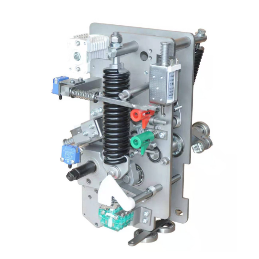
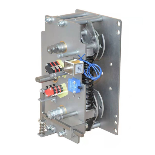
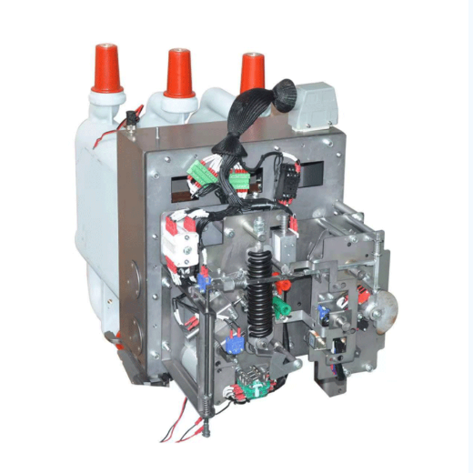
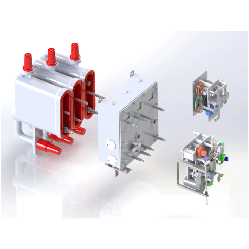
Overview This spring operated circuit breaker mechanism is suitable for use in 12kV AC metal-enclosed switchgear with isolating mechanism.The mechanism adopts the mode of tension spring over-center control to realize the transmission of three working positions of closing-opening-grounding.The rotation angle of the main shaft of the fitting body of the mechanism is 45°~80°.The mechanism opening spring and cushion oil cup sealing box are designed in front, which is convenient for debugging, testing and maintenance.
Operation Specification
Tap-off ground: close the cable chamber door, press the switch-off button, or press the electric switch-off button to open the circuit breaker, and move the unlocking lever to the right
At the position of "grounding ", insert the crank into the grounding operation hole, turn the crank clockwise for 15 circles until the crank is still, and pull out the crank.Close and isolate: move the unlocking lever to the "isolated" position to the left, insert the handle into the isolation operation hole, first turn the handle clockwise by 1/10 circles, then turn the handle counterclockwise by 17.5 circles until the handle is still, and pull out the handle.
Unlock: Move the unlock lever to the right to the "Unlock" position.
Closing the circuit breaker: insert the crank into the energy storage hole, swing the crank clockwise, or press the electric energy storage button. After hearing the "Pa" sound, the energy storage is in place. Press the closing button or the electric closing button to close the circuit breaker.
Power-off operation: press the opening button or press the electric opening button to open the circuit breaker
Overhaul:
Separation: move the unlocking handle to the "isolation" position to the left, insert the handle into the isolation operation hole, and turn the handle clockwise for 17.5 circles until the handle does not move and pull out the handle.
Close the grounding: move the unlocking handle to the right to the "grounding" position, insert the crank into the grounding operation hole, first turn the crank clockwise for 110 circles, then turn the crank counterclockwise for 15 circles until the crank is not moved, and pull out the crank to unlock: move the unlocking handle to the left to the "unlocking" position.
Closing the circuit breaker: insert the crank into the energy storage hole, turn the crank clockwise, or press the electric energy storage button. After the sound of "crack" is heard, the energy storage is in place. Press the closing button or the electric closing button to close the circuit breaker.Open the cable room for maintenance.
Outline installation dimension drawing of mechanism:

-
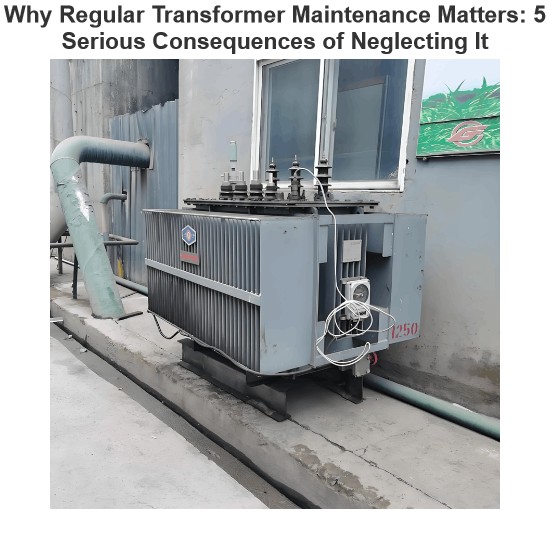 Why Regular Transformer Maintenance Matters: 5 Serious Consequences of Neglecting ItI. Allowable TemperatureWhen a transformer is in operation, its windings and iron core generate copper loss and iron loss. These losses are converted into heat energy, causing the temperature of the transformer's iron core and windings to rise. If the temperature exceeds the allowable value for a long time, the insulation will gradually lose its mechanical elasticity and age.The temperature of each part of the transformer during operation is different: the winding temperature is the highest, folRockwell09/12/2025
 -
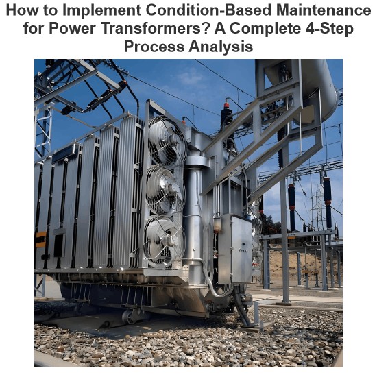 How to Implement Condition-Based Maintenance for Power Transformers? A Complete 4-Step Process Analysis1. Definition of Condition-Based MaintenanceCondition-based maintenance refers to a maintenance method where decisions on whether and how to perform maintenance are determined based on the real-time operating status and health condition of equipment. It has no fixed maintenance methods or schedules. The prerequisite for condition-based maintenance is the establishment of equipment parameters and the comprehensive analysis of various operational information of the equipment, so as to make reasonaNoah09/12/2025
 -
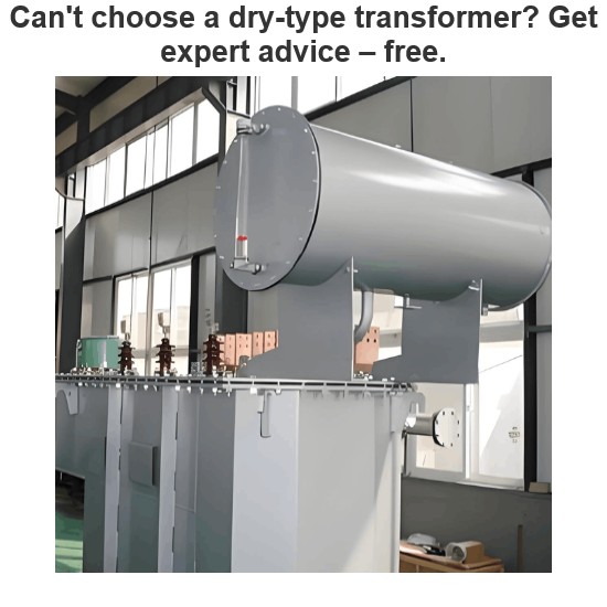 Can't choose a dry-type transformer? Get expert advice – free.Traction Rectifier TransformersRated capacity: 800 to 4400 kVA; Voltage class: 10 kV and 35 kV; Rectifier pulse number: 12-pulse and 24-pulse. Compared with 12-pulse rectifier circuits, 24-pulse rectifier circuits can reduce the harmonic pollution of the power grid by 50%, and no filtering equipment is needed at this location. It is suitable for power supply systems of urban subways and rail transit.Excitation Rectifier TransformersRated capacity: 315 to 3000 × 3 kVA; Voltage class: 10 kV, 13.8Vziman09/12/2025
 -
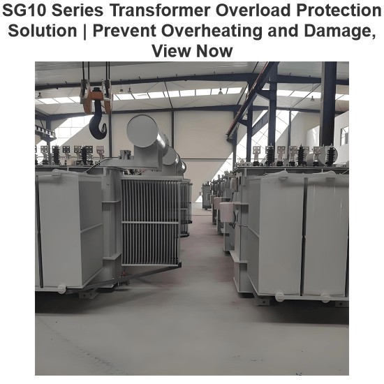 SG10 Series Transformer Overload Protection Solution | Prevent Overheating and Damage, View NowOperating Conditions in National Standard GB 6450-1986Ambient temperature: Maximum ambient temperature: +40°C Daily average maximum temperature: +30°C Annual average maximum temperature: +20°C Minimum temperature: -30°C (outdoor); -5°C (indoor) Horizontal axis: Product load; Vertical axis: Average coil temperature rise in Kelvin (note: not in Celsius).For Class H insulation products, the long-term temperature resistance of insulation materials is stipulated by the state as 180°C. However, the inRockwell09/12/2025
 -
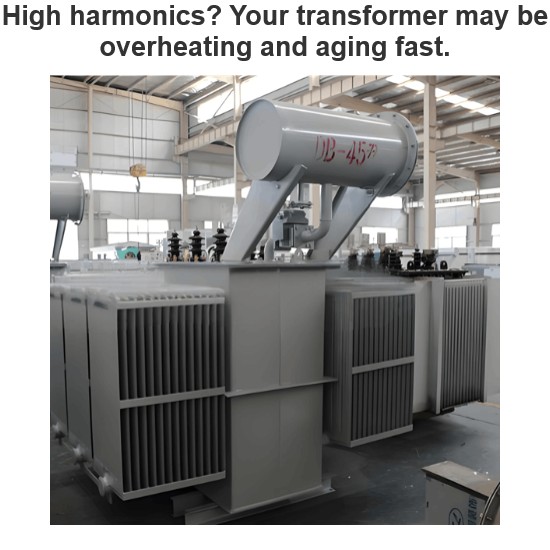 High harmonics? Your transformer may be overheating and aging fast.This report is based on the analysis of one-day power quality monitoring data of your company's distribution system. The data shows that there is significant three-phase current harmonic distortion in the system (with a high total harmonic distortion of current, THDi). In accordance with international standards (IEC/IEEE), harmonic currents at this level have posed substantial risks to the safe, reliable, and economical operation of the power supply transformer, mainly manifested in additional hLeon09/12/2025
 -
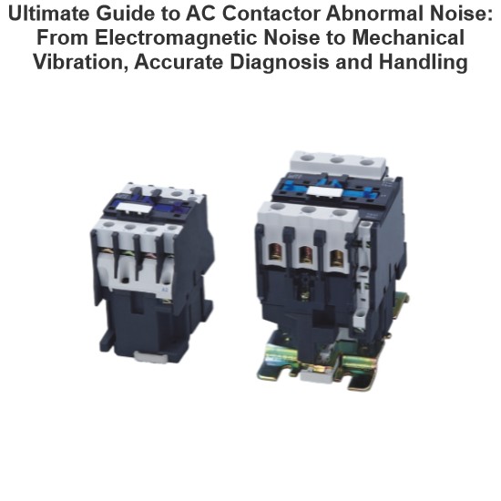 Ultimate Guide to AC Contactor Abnormal Noise: From Electromagnetic Noise to Mechanical Vibration, Accurate Diagnosis and HandlingIn electrical control systems, AC contactors are among the commonly used electrical components, and they are also a common source of various electrical faults. After long-term use—especially in harsh environments with high levels of dust—AC contactors may sometimes emit squeaking or rattling noises after being pulled in and held. The causes of this phenomenon are analyzed as follows.Squeaking Noise After Pull-In and HoldingA fully functional AC contactor makes no noise when energized and pulledFelix Spark09/11/2025