DS4 40.5kV 126kV 145kV 252kV High voltage disconnect switch
Key attributes
| Brand | ROCKWILL |
| Model NO. | DS4 40.5kV 126kV 145kV 252kV High voltage disconnect switch |
| Rated voltage | 252kV |
| Rated normal current | 3150A |
| Series | DS4 |
Product descriptions from the supplier
Description:
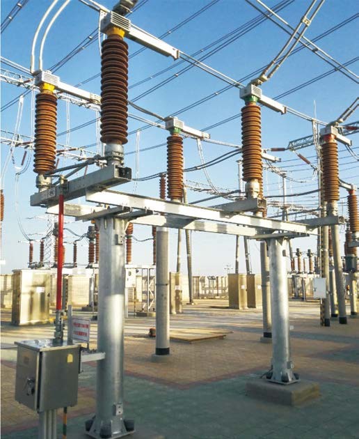
DS4 series disconnector adopts double column horizontal rotation structure, which is composed of three unipolar and operating mechanism. Each monopole consists of a base, a post insulator, and a conducting part. A rotating pillar insulator is installed at both ends of the base, and the contact arm and contact arm of the main electrical part are respectively fixed on the top of the pillar insulator. The operating mechanism drives one end of the pillar insulator to rotate, and drives the other end of the pillar insulator to reverse rotate 90° through the cross connecting rod, so that the conductive knife can turn on the horizontal plane to realize the isolation switch opening and closing. The opening state forms a horizontal insulation fracture.
Main Features:
-
The conductive arm is made of rectangular aluminum alloy tube or aluminum alloy plate, high strength, light weight, large heat dissipation area, good anti-corrosion performance.
-
The contact part of the conductive arm adopts external pressure plate spring structure. The plate spring is made of alloy material with good elasticity, which can keep the contact pressure stable for a long time and overcome the drawbacks of the spring internal pull structure.
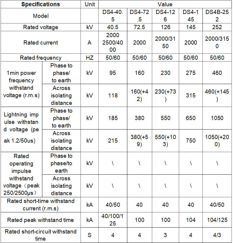
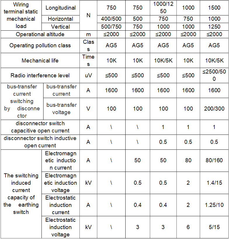
Technical parameter
What are the structural characteristics of the disconnector?
Contact System:
-
Description: The contact system is a critical part of the isolator switch, consisting of moving contacts and stationary contacts. The moving contact is typically connected to the operating handle via a transmission mechanism and can move to engage or disengage from the stationary contact under the influence of the operating force.
-
Surface Treatment: To ensure good contact performance, the contact surfaces are often specially treated, such as silver plating. This reduces contact resistance and minimizes heat generation.
-
Shape Design: The shape of the contacts is also important. Common types include knife-blade contacts and finger contacts, which provide a larger contact area to ensure safe and stable current flow.
Insulation Part:
-
Description: The insulation part ensures that there is sufficient insulation between different potential sections of the isolator switch. It is mainly composed of insulators, which are typically made of ceramic, glass, or composite materials.
-
Ceramic Insulators: Ceramic insulators have excellent insulation properties, mechanical strength, and weather resistance, making them suitable for various harsh environmental conditions.
-
Glass Insulators: Glass insulators have good self-cleaning properties, reducing the impact of dust and dirt on insulation performance.
-
Composite Insulators: Composite insulators are lightweight and have excellent pollution flashover resistance, making them advantageous in special application scenarios.
Transmission Mechanism:
-
Description: The transmission mechanism is used to transfer the operating force from the operating handle to the moving contact, enabling the opening and closing actions of the contacts. It can be a manual linkage mechanism or an electric operating mechanism.
-
Manual Linkage Mechanism: This type of mechanism is simple in structure and highly reliable. It converts the rotational motion of the operating handle into linear or rotational motion of the moving contact through a series of linkages and shafts.
-
Electric Operating Mechanism: Suitable for applications requiring remote control or frequent operation, this mechanism uses a motor, reduction gear, and transmission components to achieve automated operation of the isolator switch.
Base and Support:
-
Description: The base and support are the supporting structures of the isolator switch, used to fix the contact system, insulation part, and transmission mechanism. The base is usually made of metal and has sufficient mechanical strength and stability to bear the weight of the isolator switch and various forces generated during operation.
-
Design Considerations: The support is designed based on the installation method and application scenario of the isolator switch. For example, the support structure of indoor isolator switches differs from that of outdoor isolator switches. Outdoor isolator switches require supports that consider factors such as wind resistance, rain protection, and corrosion resistance.

Related Products


Related Knowledges
-
 What Are the Handling Procedures After Transformer Gas (Buchholz) Protection Activation?What Are the Handling Procedures After Transformer Gas (Buchholz) Protection Activation?When the transformer gas (Buchholz) protection device operates, a thorough inspection, careful analysis, and accurate judgment must be carried out immediately, followed by appropriate corrective actions.1. When the Gas Protection Alarm Signal is ActivatedUpon activation of the gas protection alarm, the transformer should be inspected immediately to determine the cause of operation. Check whether it was causedFelix Spark11/01/2025
 -
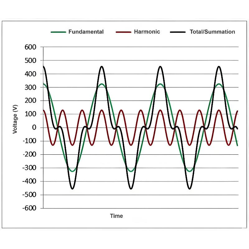
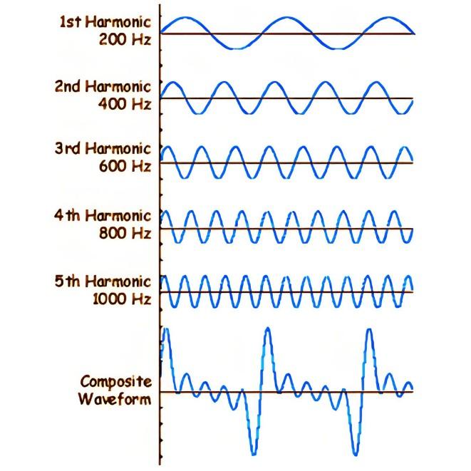
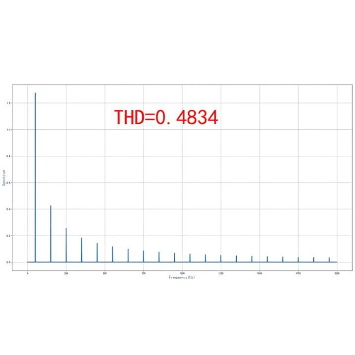 What Is THD? How It Affects Power Quality & EquipmentIn the field of electrical engineering, the stability and reliability of power systems are of paramount importance. With the advancement of power electronics technology, the widespread use of nonlinear loads has led to an increasingly serious problem of harmonic distortion in power systems.Definition of THDTotal Harmonic Distortion (THD) is defined as the ratio of the root mean square (RMS) value of all harmonic components to the RMS value of the fundamental component in a periodic signal. It isEncyclopedia11/01/2025
 -
 THD Overload: How Harmonics Destroy Power EquipmentWhen Actual Grid THD Exceeds Limits (e.g., Voltage THDv > 5%, Current THDi > 10%), It Causes Organic Damage to Equipment Across the Entire Power Chain — Transmission → Distribution → Generation → Control → Consumption. The Core Mechanisms Are Additional Losses, Resonant Overcurrent, Torque Fluctuations, and Sampling Distortion. Damage Mechanisms and Manifestations Vary Significantly by Equipment Type, as Detailed Below:1. Transmission Equipment: Overheating, Aging, and Drastically ReducedEcho11/01/2025
 -
 Harmonic THD Impact: From Grid to EquipmentThe impact of harmonic THD errors on power systems must be analyzed from two aspects: "actual grid THD exceeding limits (excessive harmonic content)" and "THD measurement errors (inaccurate monitoring)" — the former directly damages system equipment and stability, while the latter leads to improper mitigation due to "false or missed alarms." When combined, these two factors amplify system risks. The impacts span the entire power chain — generation → transmission → distribution → consumption — afEdwiin11/01/2025
 -
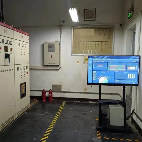 Intelligent Electrical Room: Key Development TrendsWhat Is the Future of Intelligent Electrical Rooms?Intelligent electrical rooms refer to the transformation and upgrading of traditional electrical distribution rooms through the integration of emerging technologies such as the Internet of Things (IoT), big data, and cloud computing. This enables 24/7 remote online monitoring of power circuits, equipment conditions, and environmental parameters, significantly improving safety, reliability, and operational efficiency.The development trends of intEcho11/01/2025
 -
 How to Inspect an Electrical Room: Complete ChecklistElectrical Room Inspection: Content and PrecautionsThe electrical room is a critical facility for power equipment, responsible for power supply, distribution, and energy output. Therefore, regular inspection of the electrical room is an essential task.1. Electrical Room Inspection Content: Check the operation and lock of entry/exit doors, ensure door gaps are tight, and verify the floor is level and free of obstructions. Monitor the room’s temperature, humidity, and odor to ensure environmentalFelix Spark11/01/2025
Related Solutions
-
 Intelligent Operation Solution for 12kV Vacuum Circuit Breakers: Integrating Real-time Monitoring & Lifetime OptimizationⅠ. Equipment Operation & MaintenanceIntelligent Monitoring System IntegrationMulti-parameter Real-time Monitoring: Embedded sensors (temperature, displacement, Hall effect current sensors) track contact temperature rise, mechanical characteristics (opening/closing speed, overtravel), coil current, and partial discharge signals. Data undergoes preprocessing via edge computing prior to cloud upload.Lifetime Prediction Model: Dynamically evaluates remaining lifespan using electrical wear dataRockwill06/10/2025
 -
 SF6 Circuit Breaker Solutions for Outdoor Installation (Anti-Pollution & Seismic Resistance)I.Core Challenges in Outdoor InstallationIn high-voltage transmission and distribution systems, SF6 circuit breakers are exposed to complex outdoor environments for extended periods, facing the following critical issues:Pollution & Insulation DegradationDust, salt fog, and industrial pollutants in outdoor environments easily adhere to equipment surfaces. In coastal or industrial areas, pollution levels may reach Class IV, resulting in insufficient creepage distance and triggering flashoRockwill05/12/2025
 -
 12kV Indoor Vacuum Circuit Breaker Southeast Asia Solution: Anti-Corrosion Compact Design12kV Indoor Vacuum Circuit Breaker Southeast Asia Solution: Anti-Corrosion Compact DesignⅠ. Executive SummarySoutheast Asia faces rapidly growing electricity demand alongside environmental challenges including high temperatures, humidity, salt spray corrosion, and grid instability. This solution recommends Solid Insulated Pole-Mounted Vacuum Circuit Breakers (VCB) featuring high reliability, compact design, and smart monitoring. Tailored for tropical climates and industrial scenarios, itRockwill06/10/2025


