| Brand | Vziman |
| Model NO. | Ferroalloy furnace transformer |
| Rated capacity | 15000KVA |
| Series | Ferroalloy furnace transformer |
Our company pursues the following four goals in transformer equipment and manufacturing:
Transformers themselves have excellent energy-saving characteristics: no-load loss, no-load current, and load loss. Try to reduce the impedance voltage percentage as much as possible, choose the appropriate impedance voltage percentage on the commonly used capacity, use existing high-quality raw materials, and use advanced technologies such as small oil gaps to make the transformer truly energy-saving, with a performance level in the mid-1990s of internationally developed country products.
Transformers have very stable reliability and a long service life. The design technology of new structure products must undergo operational testing and type testing verification, with a design life of no less than thirty years.
Require a certain overload capacity to ensure that all operational indicators meet the national standard requirements when users exceed the rated capacity by 20%.
Reduce the maintenance workload of users, prevent them from hanging cores during long-term use, and design a maintenance free time of no less than ten years. The free maintenance period is twenty years.
Selection of transformer materials, structures, and processes:
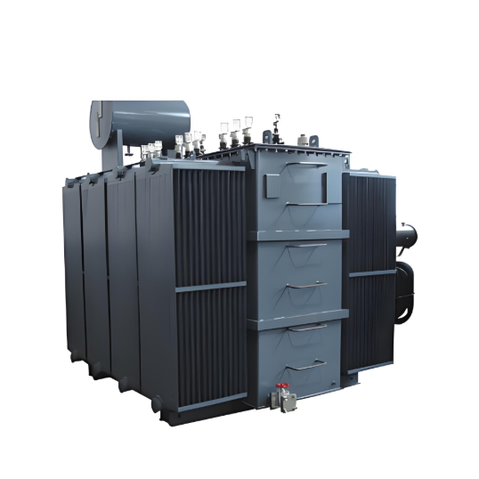
A complete ferroalloy furnace transformer is mainly divided into the following six parts:
Namely: iron core, winding, body, oil tank, final assembly, accessories. Below are the separate introductions、
Iron core: In terms of materials, we have selected either BaoWu Steel's 30Q130 or Nippon Steel's 30Z130 silicon steel sheet, which is basically consistent with the materials used in internationally developed countries.
The structure adopts a fully inclined seam plate type, and the connection between the upper and lower clamps adopts a low magnetic steel plate pull plate structure, changing the previous square iron structure to ensure that there are no holes or defects on the iron chip, the magnetic flux density of each section of the iron core is consistent, and there is no distortion. In the shear process, German imported Georg shear lines are used to control the shear burrs to be less than 0.02mm (standard<0.05mm is qualified), and the length tolerance per meter is less than 0.02mm, thereby increasing the lamination coefficient and reducing the gap between the seams, It avoids local overheating of the iron core, reduces product noise, no-load loss, and no-load current.
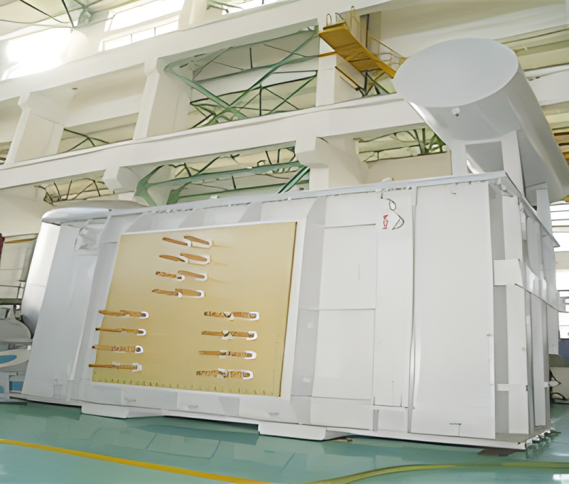
Winding: Oxygen free copper electromagnetic wire is used from the material, mainly controlling its ρ 20 ℃<0.017241, in addition, the main control is the material and tightness of the paper wrapped insulation, while other insulation materials have been greatly improved. The main purpose is to make the coil have good axial and radial stability as much as possible, and to improve its overload capacity and thermal stability. The loss has also decreased.
Body: All wooden components of the body have been changed to laminated wood, improving the stiffness of the lead frame. The upper and lower pressing plates are made of cardboard or epoxy resin molded parts, which increases the insulation distance between the electrical conductor and the ground compared to iron pressing plates and can reduce the size of the "window height". 1、 The secondary main insulation adopts imported cardboard, which increases the strength of the main insulation. The multi coil adopts an overall package, which improves the reliability of the product. The drying of the device body adopts Norwegian vapor phase drying equipment, which is thorough and does not damage the insulation, and has the function of flushing the device body.
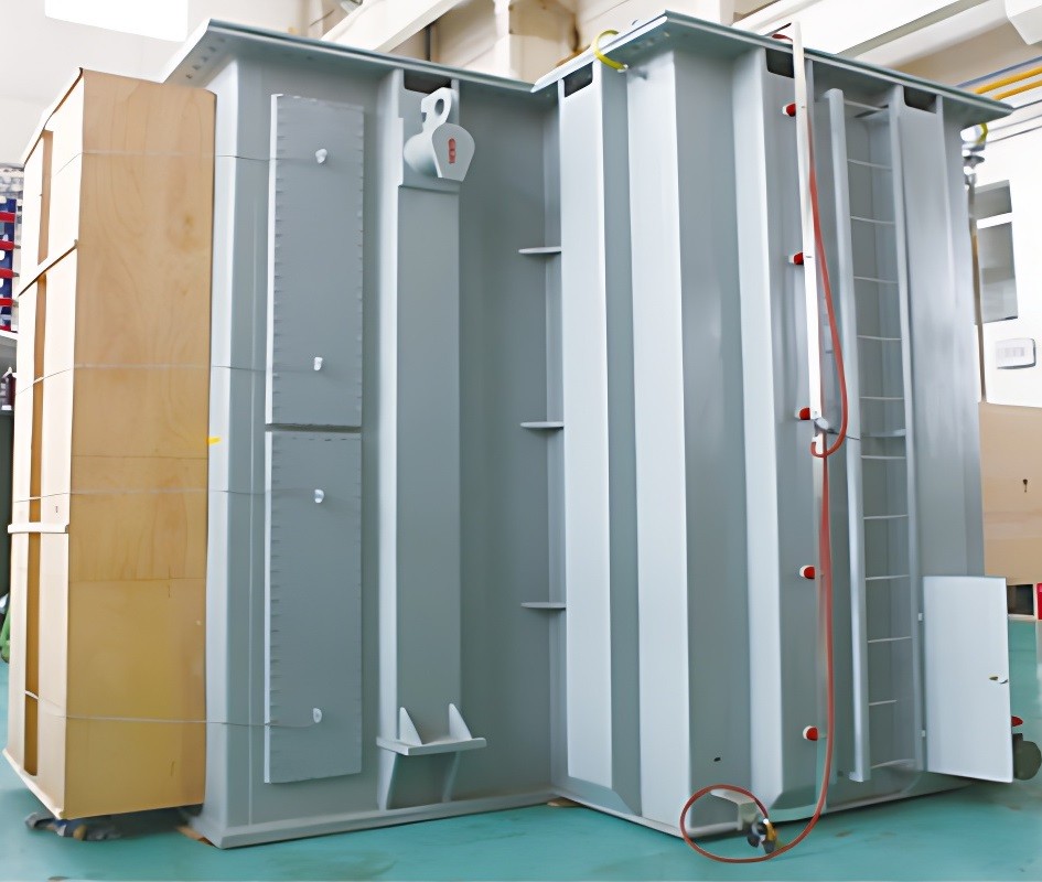
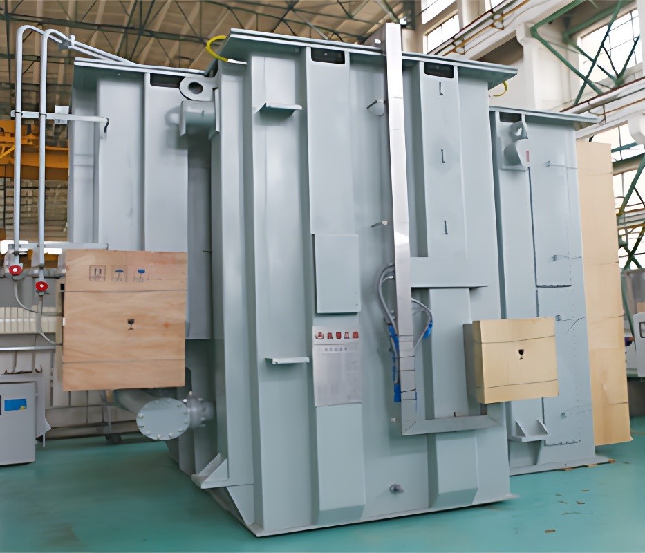
Fuel tank: The fuel tank adopts a folded plate type. Minimize welding seams as much as possible, increase strength, and conduct positive and negative pressure tests to ensure the reliability of product sealing.
General assembly: After the body is dry, the winding loosens and is compressed with hydraulic equipment, achieving good results. Vacuum oil injection is used to reduce air bubbles in the product winding, reduce partial discharge, and increase product life. Using new anti-aging sealing materials, the original leakage problem can be improved.
Attachment: The main accessory water cooler is YS1 type oil water cooler, which is equipped with a descaling device instead of water quality. It can be installed separately or directly fixed on the transformer host (which can reduce installation work and floor space). The cooler is equipped with a control box, oil and water flow relays, and oil water pressure differential relays. The on load tap changer adopts domestic switches and is equipped with remote gear display.
The transformer oil is naphthenic anti-aging transformer oil produced in Karamay, and the oil protection is fully enclosed structure (that is, the pressure relief valve is equipped with diaphragm oil conservator structure)
About Transformer Maintenance:
It is necessary to use the suspended core after the product arrives for long-distance transportation, mainly to solve the problems of loose fasteners during transportation and user acceptance of the manufacturer's products. However, regarding routine major repairs, we believe that it is necessary to inspect and replace those mechanical wear parts according to the original major repair cycle. For operating components such as pumps, it is not necessary to suspend the core inside relatively stationary transformers for a long time. Only monitoring the quality changes of oil such as gas chromatography is sufficient to grasp the condition of the transformer body, thereby saving maintenance costs and reducing the pollution of the transformer body and oil caused by suspended cores.
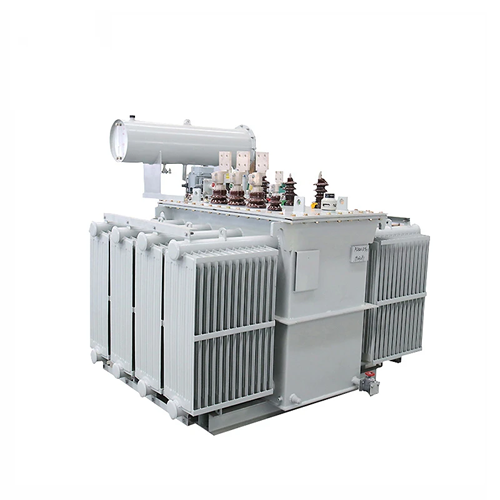
Appearance characteristics:
In the design, the product structure is made compact, and various transformer control lines are connected to a unified junction box and explained for use, making it aesthetically pleasing and easy to operate.
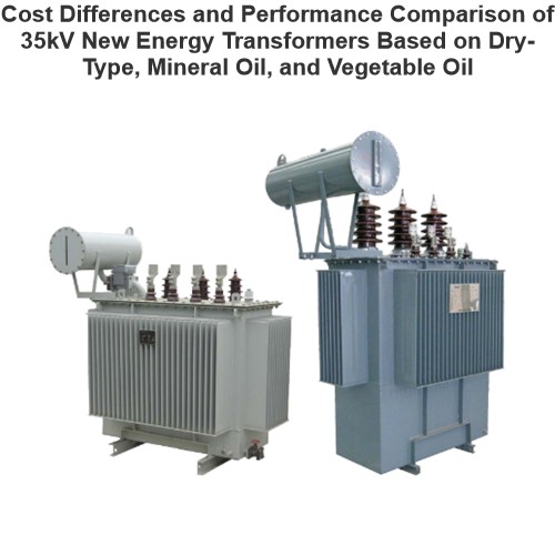
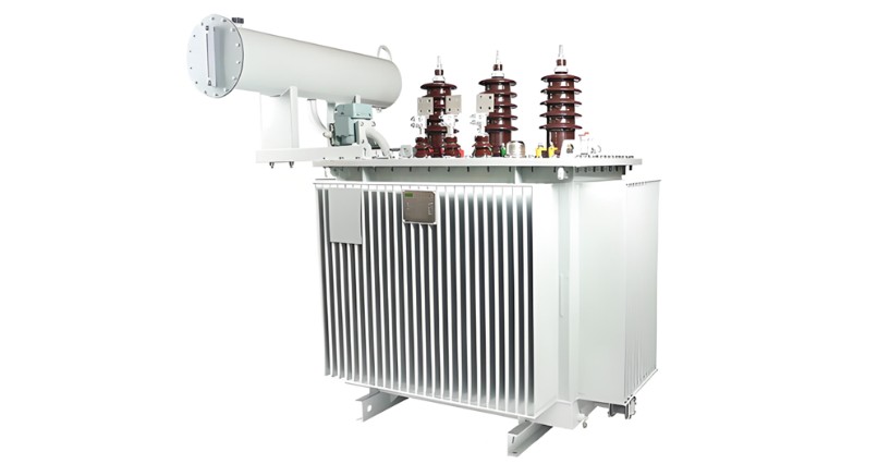
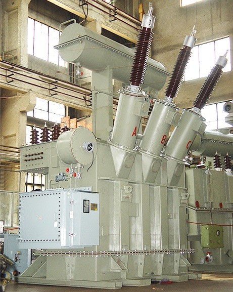
What is a ferroalloy furnace transformer?
The ferroalloy furnace transformer is a special type of transformer specifically designed for ferroalloy furnaces. It is used to convert the high-voltage electrical energy provided by the power grid into low-voltage, high-current electrical energy suitable for the operation of ferroalloy furnaces. Ferroalloy furnaces are widely used in the metallurgical industry to produce various ferroalloys, such as ferrosilicon, ferromanganese, and ferrochrome. These alloys play an important role in steel production and can improve the properties of steel. The following is a detailed explanation of the ferroalloy furnace transformer:
Definition and Characteristics:
Definition: The ferroalloy furnace transformer is a transformer specifically designed for ferroalloy furnaces, used to convert the high-voltage electrical energy of the power grid into low-voltage, high-current electrical energy suitable for the operation of ferroalloy furnaces.
Characteristics:
High Current Output: It can provide a large current to meet the high-power requirements of ferroalloy furnaces.
Low Voltage Output: The output voltage is usually low to meet the working requirements of ferroalloy furnaces.
High Heat Resistance: The ferroalloy furnace transformer needs to work in a high-temperature environment, so it has good heat-resistant properties.
High Reliability: The ferroalloy furnace transformer needs to operate continuously for a long time, so it has high reliability and a long service life.
High Efficiency: It adopts high-quality materials and advanced manufacturing processes, having high efficiency and reducing energy loss.
Multiple Protection Measures: It is equipped with various protection devices to ensure safe operation.