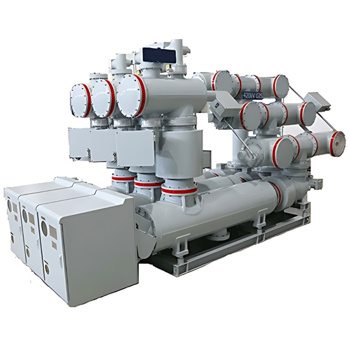
Hybrid Gas Insulated Switchgear up to 145kV

Key attributes
| Brand | ROCKWILL |
| Model NO. | Hybrid Gas Insulated Switchgear up to 145kV |
| Rated voltage | 72.5kV |
| Rated normal current | 2000A |
| Rated short circuit breaking current | 31.5kA |
| Series | RHP |
Product descriptions from the supplier
Product overview
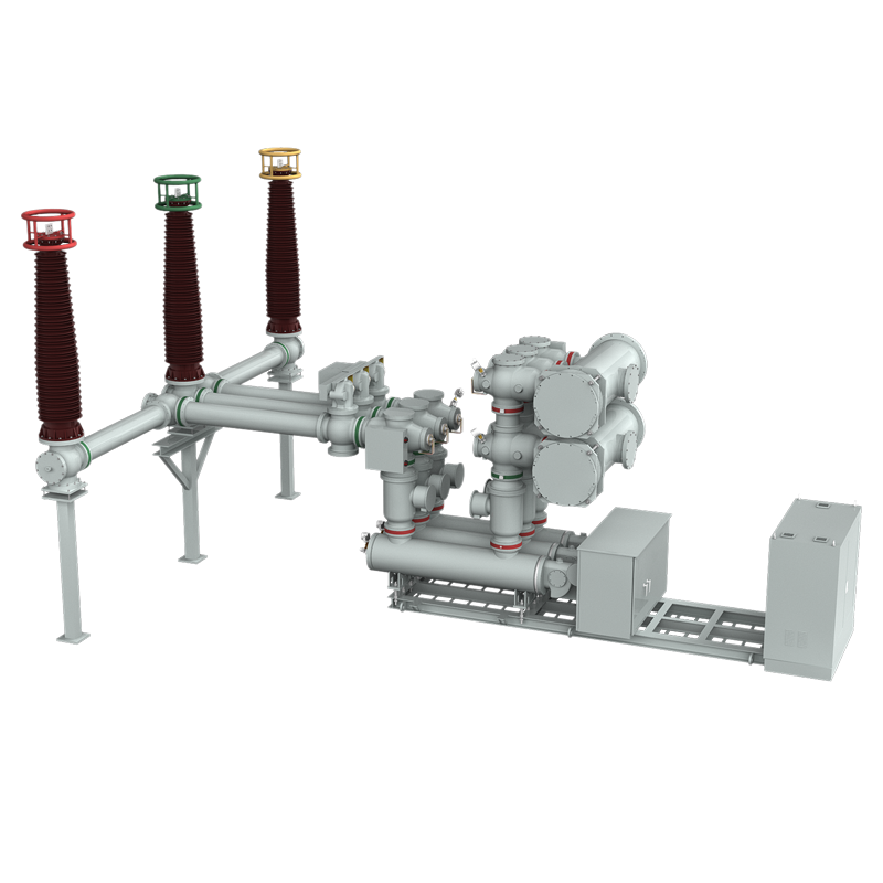
The RHP type HGIS electrical apparatus is a new type of high-voltage power equipment. It retains the advantages of GIS combined electrical apparatus, such as compactness, high reliability, and low operation and maintenance requirements, while innovatively retaining the busbar as a conventional AIS arrangement for on-site installation and connection. This design effectively overcomes the drawbacks associated with traditional AIS equipment, including large footprint, numerous connection points, and high inspection and maintenance workloads.
It is suitable for 40.5kV up to145kV and below transmission and distribution systems in power plants, substations, railway stations, ports, and large industrial and mining enterprises. It is particularly well-suited for space-constrained projects such as mountainous substations and urban substations, and can be installed indoors, outdoors, or on rooftops.
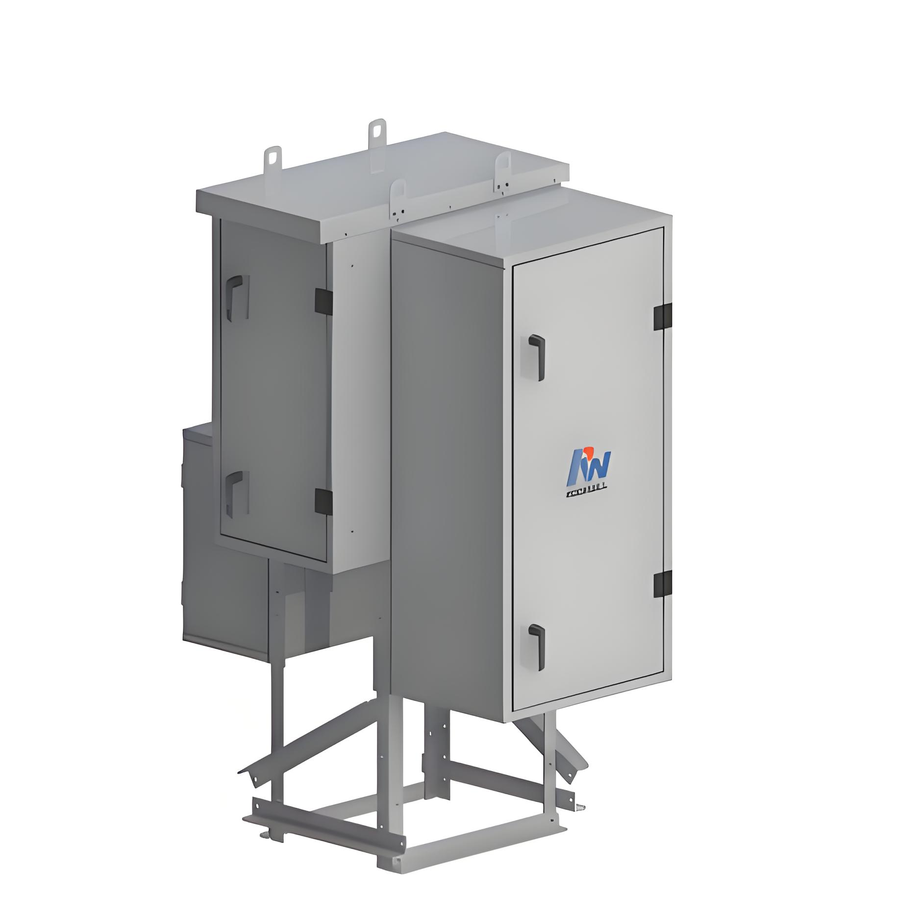
Product Component
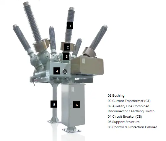
Mian features
Genuine Solution to Operational Reliability Challenges in Disconnector/Earthing Switches;
Advanced Self-Blast Interruption and Modular Structure for Enhanced Reliability;
The elimination or significant reduction of disc-type insulators for enhanced reliability;
The application of specialized manufacturing techniques reduces the number of flanges, thereby minimizing the potential for gas leakage;
Externally Mounted CT for enhanced safety and reliability;
Compact Structure and Flexible Layout;
Relatively more economical than AIS.
Technical Parameters
RHP-40.5
N |
Item |
Unit |
Parameters |
1 |
Rated maximum voltage |
kV |
40.5 |
2 |
Rated maximum current |
A |
≤2000 |
3 |
Rated frequency |
Hz |
50/60 |
4 |
First opening pole coefficient |
|
1.5 |
5 |
Rated short circuit breaking current |
kA |
31.5 |
6 |
Rated short-circuit duration |
s |
4 |
7 |
Rated out of step breaking current |
kA |
7.9 |
8 |
Rated peak value withstand current |
kA |
80 |
9 |
Rated 1min power frequency withstand voltage (Dry/Wet) |
kV |
To ground 110 |
Break 118 |
|||
10 |
Rated lightning impulse voltage |
kV |
To ground 215 |
Break 215 |
|||
11 |
Operation sequence |
|
O-0.3s-CO-180s-CO |
12 |
Opening time |
ms |
50±10 |
13 |
Closing time |
ms |
90±20 |
14 |
Close-open time |
ms |
≤100 |
15 |
Main circuit resistance |
μΩ |
≤150 |
16 |
Rated SF6 gas pressure (20℃gauge pressure) |
Mpa |
0.5 |
17 |
Alarm/blocking pressure(20℃gauge pressure) |
Mpa |
0.45/0.4 |
18 |
SF6 annual gas leakage rate |
% |
≤0.5 |
19 |
Gas moisture content |
Ppm(v) |
≤150 |
20 |
Mechanical life |
times |
6000 |
RHP-72.5
N |
Item |
Unit |
Parameters |
1 |
Rated maximum voltage |
kV |
72.5 |
2 |
Rated maximum current |
A |
≤3150 |
3 |
Rated frequency |
Hz |
50/60 |
4 |
First opening pole coefficient |
|
1.5 |
5 |
Rated short circuit breaking current |
kA |
40 |
6 |
Rated short-circuit duration |
s |
4 |
7 |
Rated out of step breaking current |
kA |
10 |
8 |
Rated peak value withstand current |
kA |
100 |
9 |
Rated 1min power frequency withstand voltage (Dry/Wet) |
kV |
To ground 275 |
Break 315 |
|||
10 |
Rated lightning impulse voltage |
kV |
To ground 650 |
Break 750 |
|||
11 |
Operation sequence |
|
O-0.3s-CO-180s-CO |
12 |
Opening time |
ms |
32±7 |
13 |
Closing time |
ms |
85±10 |
14 |
Close-open time |
ms |
≤60 |
15 |
Main circuit resistance |
μΩ |
≤100 |
16 |
Rated SF6 gas pressure (20℃gauge pressure) |
Mpa |
0.5 |
17 |
Alarm/blocking pressure(20℃gauge pressure) |
Mpa |
0.55/0.5 |
18 |
SF6 annual gas leakage rate |
% |
≤0.5 |
19 |
Gas moisture content |
Ppm(v) |
≤150 |
20 |
Mechanical life |
times |
6000 |
RHP-145
N |
Item |
Unit |
Parameters |
1 |
Rated maximum voltage |
kV |
145 |
2 |
Rated maximum current |
A |
≤3150 |
3 |
Rated frequency |
Hz |
50/60 |
4 |
First opening pole coefficient |
|
1.5 |
5 |
Rated short circuit breaking current |
kA |
40 |
6 |
Rated short-circuit duration |
s |
4 |
7 |
Rated out of step breaking current |
kA |
10 |
8 |
Rated peak value withstand current |
kA |
100 |
9 |
Rated 1min power frequency withstand voltage (Dry/Wet) |
kV |
To ground 275 |
Break 315 |
|||
10 |
Rated lightning impulse voltage |
kV |
To ground 650 |
Break 750 |
|||
11 |
Operation sequence |
|
O-0.3s-CO-180s-CO |
12 |
Opening time |
ms |
32±7 |
13 |
Closing time |
ms |
85±10 |
14 |
Close-open time |
ms |
≤60 |
15 |
Main circuit resistance |
μΩ |
≤100 |
16 |
Rated SF6 gas pressure (20℃gauge pressure) |
Mpa |
0.5 |
17 |
Alarm/blocking pressure(20℃gauge pressure) |
Mpa |
0.55/0.5 |
18 |
SF6 annual gas leakage rate |
% |
≤0.5 |
19 |
Gas moisture content |
Ppm(v) |
≤150 |
20 |
Mechanical life |
times |
6000 |
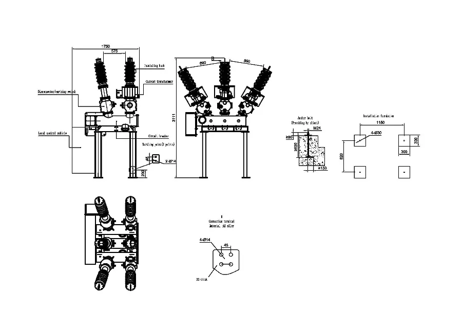
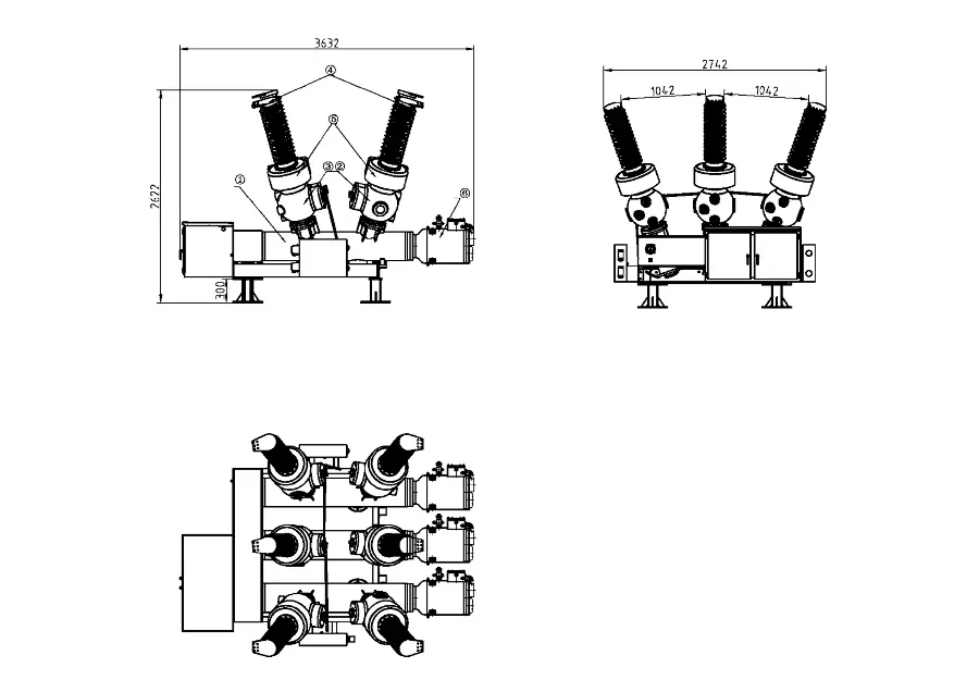
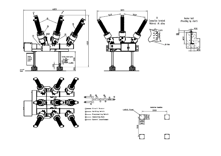
Dimension
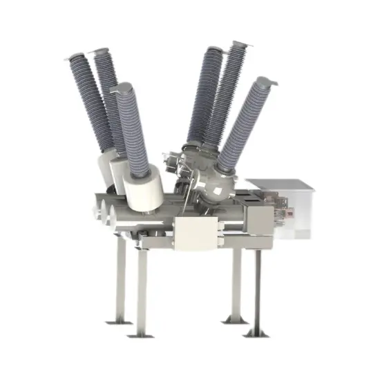
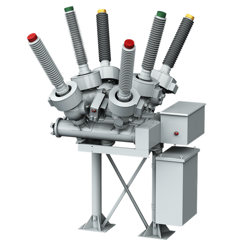
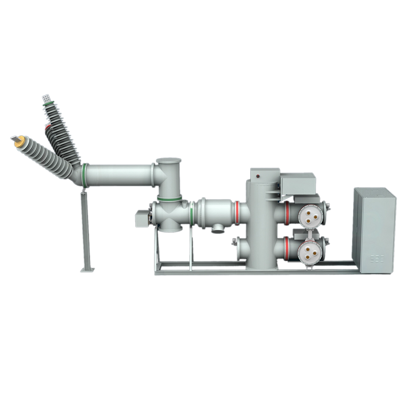
40.5kV
72.5kV
145kV
- Full digitalization: Information collection, transmission, and processing are all digital, with fiber optic cables replacing cables;
- High compatibility: Following the IEC 61850 standard, devices are interconnected and interoperable;
- Easy to expand: New features do not require modification of existing devices, only need to be connected to the network.
The voltage covers 40.5kV-145kV and is suitable for scenarios such as power plants, substations, railways, ports, etc. It is particularly suitable for space limited projects such as urban/mountainous substations, renovation of old stations, and rooftop/mobile substations.
- Land saving: 40% -60% footprint savings compared to AIS;
- Cost advantage: 30% lower than GIS investment and 45% -50% lower than total investment;
- Less maintenance: 25 years maintenance free, mechanical lifespan of 6000 times;
- Environmental Protection: SF6 usage is only 20% of GIS, with an annual leakage rate of ≤ 0.5%.

Related Products
-
ZHW Series HV Gas insulation switchgear (GIS)
-
ZFW34 HV Gas insulation switchgear (GIS)
-
ZFW21 HV Gas insulation switchgear (GIS)
-
12kV 17.5kV 24kV outdoor Gas Insulated Ring Main Unit
-
KGC-1189Desktop Dissolved Gas Analysis Analyzer

-
550kV Gas Insulated Switchgear HV (GIS)

-
420kV HV Gas Insualted Switchgear(GIS)
Related Knowledges
-
 HECI GCB for Generators – Fast SF6 Circuit Breaker1.Definition and Function1.1 Role of the Generator Circuit BreakerThe Generator Circuit Breaker (GCB) is a controllable disconnect point located between the generator and the step-up transformer, serving as an interface between the generator and the power grid. Its primary functions include isolating generator-side faults and enabling operational control during generator synchronization and grid connection. The operating principle of a GCB is not significantly different from that of a standard c01/06/2026
 -
 Distribution Equipment Transformer Testing, Inspection, and Maintenance1.Transformer Maintenance and Inspection Open the low-voltage (LV) circuit breaker of the transformer under maintenance, remove the control power fuse, and hang a “Do Not Close” warning sign on the switch handle. Open the high-voltage (HV) circuit breaker of the transformer under maintenance, close the grounding switch, fully discharge the transformer, lock the HV switchgear, and hang a “Do Not Close” warning sign on the switch handle. For dry-type transformer maintenance: first clean the porcel12/25/2025
 -
 How to Test Insulation Resistance of Distribution TransformersIn practical work, insulation resistance of distribution transformers is generally measured twice: the insulation resistance between thehigh-voltage (HV) windingand thelow-voltage (LV) winding plus the transformer tank, and the insulation resistance between theLV windingand theHV winding plus the transformer tank.If both measurements yield acceptable values, it indicates that the insulation among the HV winding, LV winding, and transformer tank is qualified. If either measurement fails, pairwise12/25/2025
 -
 Design Principles for Pole-Mounted Distribution TransformersDesign Principles for Pole-Mounted Distribution Transformers(1) Location and Layout PrinciplesPole-mounted transformer platforms should be located near the load center or close to critical loads, following the principle of “small capacity, multiple locations” to facilitate equipment replacement and maintenance. For residential power supply, three-phase transformers may be installed nearby based on current demand and future growth projections.(2) Capacity Selection for Three-Phase Pole-Mounted Tr12/25/2025
 -
 Transformer Noise Control Solutions for Different Installations1.Noise Mitigation for Ground-Level Independent Transformer RoomsMitigation Strategy:First, conduct a power-off inspection and maintenance of the transformer, including replacing aged insulating oil, checking and tightening all fasteners, and cleaning dust from the unit.Second, reinforce the transformer foundation or install vibration isolation devices—such as rubber pads or spring isolators—selected based on the severity of vibration.Finally, strengthen sound insulation at weak points of the ro12/25/2025
 -
 Risk Identification and Control Measures for Distribution Transformer Replacement Work1.Electric Shock Risk Prevention and ControlAccording to typical design standards for distribution network upgrades, the distance between the transformer’s drop-out fuse and the high-voltage terminal is 1.5 meters. If a crane is used for replacement, it is often impossible to maintain the required minimum safety clearance of 2 meters between the crane boom, lifting gear, slings, wire ropes, and the 10 kV live parts, posing a severe risk of electric shock.Control Measures:Measure 1:De-energize th12/25/2025
Related Solutions
-
 Intelligent Operation Solution for 12kV Vacuum Circuit Breakers: Integrating Real-time Monitoring & Lifetime OptimizationⅠ. Equipment Operation & MaintenanceIntelligent Monitoring System IntegrationMulti-parameter Real-time Monitoring: Embedded sensors (temperature, displacement, Hall effect current sensors) track contact temperature rise, mechanical characteristics (opening/closing speed, overtravel), coil current, and partial discharge signals. Data undergoes preprocessing via edge computing prior to cloud upload.Lifetime Prediction Model: Dynamically evaluates remaining lifespan using electrical wear data06/10/2025
 -
 SF6 Circuit Breaker Solutions for Outdoor Installation (Anti-Pollution & Seismic Resistance)I.Core Challenges in Outdoor InstallationIn high-voltage transmission and distribution systems, SF6 circuit breakers are exposed to complex outdoor environments for extended periods, facing the following critical issues:Pollution & Insulation DegradationDust, salt fog, and industrial pollutants in outdoor environments easily adhere to equipment surfaces. In coastal or industrial areas, pollution levels may reach Class IV, resulting in insufficient creepage distance and triggering flasho05/12/2025
 -
 12kV Indoor Vacuum Circuit Breaker Southeast Asia Solution: Anti-Corrosion Compact Design12kV Indoor Vacuum Circuit Breaker Southeast Asia Solution: Anti-Corrosion Compact DesignⅠ. Executive SummarySoutheast Asia faces rapidly growing electricity demand alongside environmental challenges including high temperatures, humidity, salt spray corrosion, and grid instability. This solution recommends Solid Insulated Pole-Mounted Vacuum Circuit Breakers (VCB) featuring high reliability, compact design, and smart monitoring. Tailored for tropical climates and industrial scenarios, it06/10/2025


