| Brand | Wone |
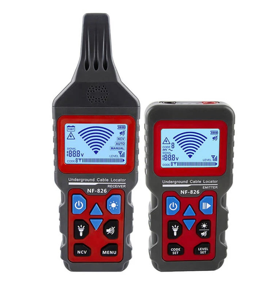
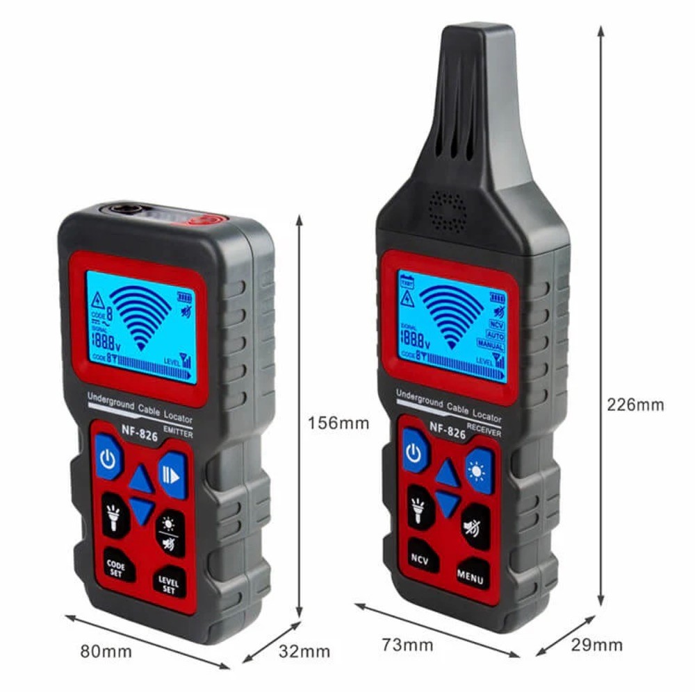
| Model NO. | NF-826 Wire Tracer for Underground and Wall Electrical Wires and Pipes |
| Max Depth Range | 1000m |
| Max Cable Length | 2m (80 inch) |
| Series | NF |
Features
Circuit Tracer: Trace circuits and find electrical wires and metal (copper, network, power) cables in drywall or underground. The Max detection range is 2m (80in).
Wiring Fault Locator: Tone locating faults like breaks, open circuits, and short circuits in wires and cables. Flexible scanning strength for various environments.
Breaker Finder: Attach the transmitter device to a socket via adapters. Locate socket breakers on the box with one tap.
Voltmeter: The transmitter has an integrated AC / DC voltmeter for linear measurement of 12-400V DC/AC voltage.
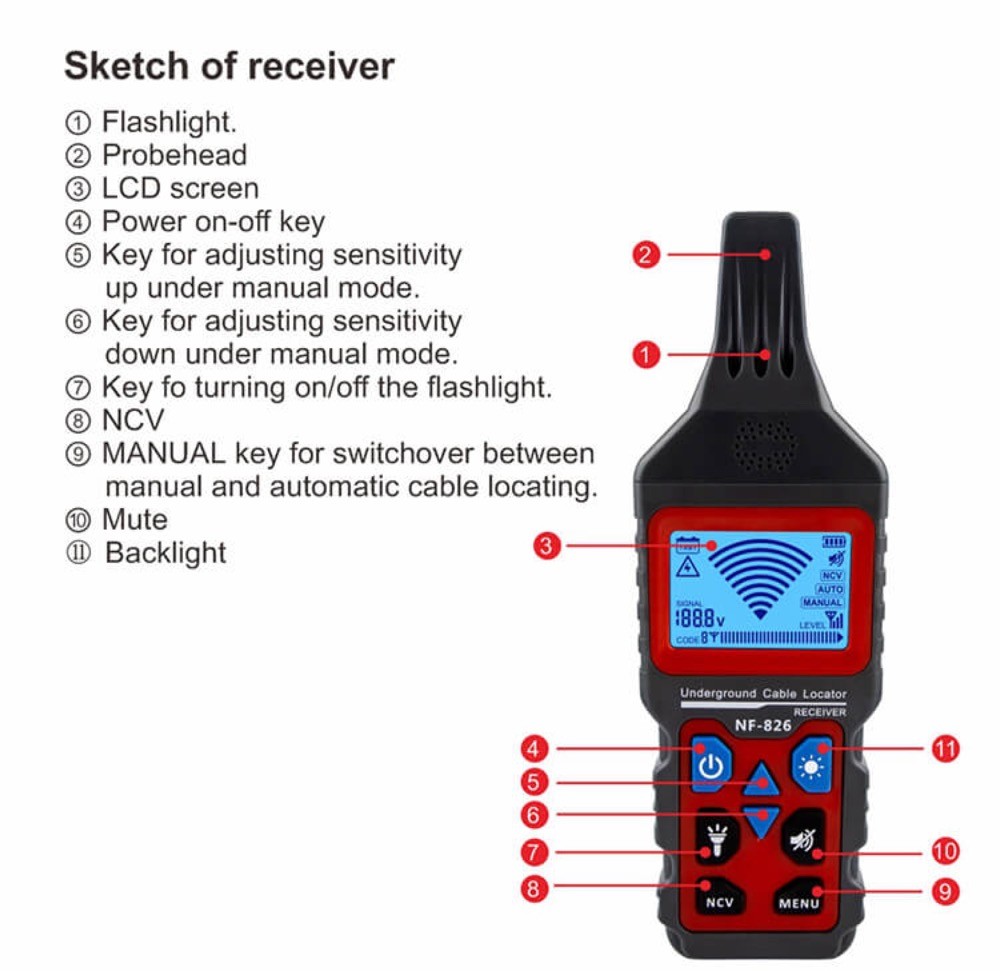
Electricity Detector: The receiver (the tone probe) can detect AC voltage over 60V without touching the object.
Pipe Locator: Detect the wiring and direction of underground water, heating, and gas pipelines without breaking the lawn and floor. Locate the breakpoints in the pipe easily.
A Built-in LED Light: An internal LED light illuminates the dark environment for easy operation.
Certification: Passes RoHS, FCC, and CE compliance testing.
Fair Price: Compared to expensive Klein and Fluke wire tracers, NF-826 is a lot more friendly to your budget.
Versatile Accessories for Precision: Provide a comprehensive set of accessories tailored for diverse scenarios, ensuring your wire tracing needs are met with precision and efficiency. Elevate your experience with our all-in-one solution for seamless connectivity troubleshooting.
Techical parameters

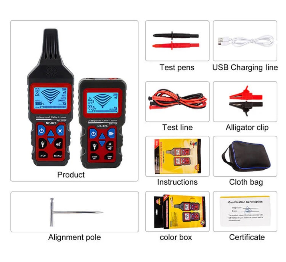
Accessories