| Brand | ROCKWILL |
| Model NO. | Outdoor RPS-15kV/1250A SF6 load break switch |
| Rated voltage | 15kV |
| Rated normal current | 1250A |
| Power frequency withstand voltage | 50Hz |
| Mainly active load breaking current | 1250A |
| Series | SF6 |
Description:
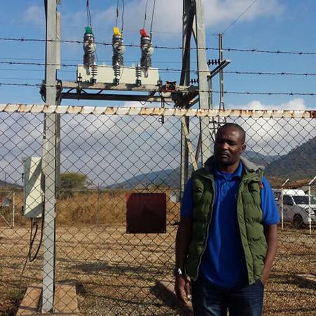
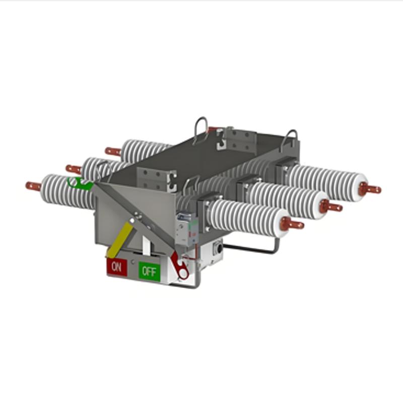
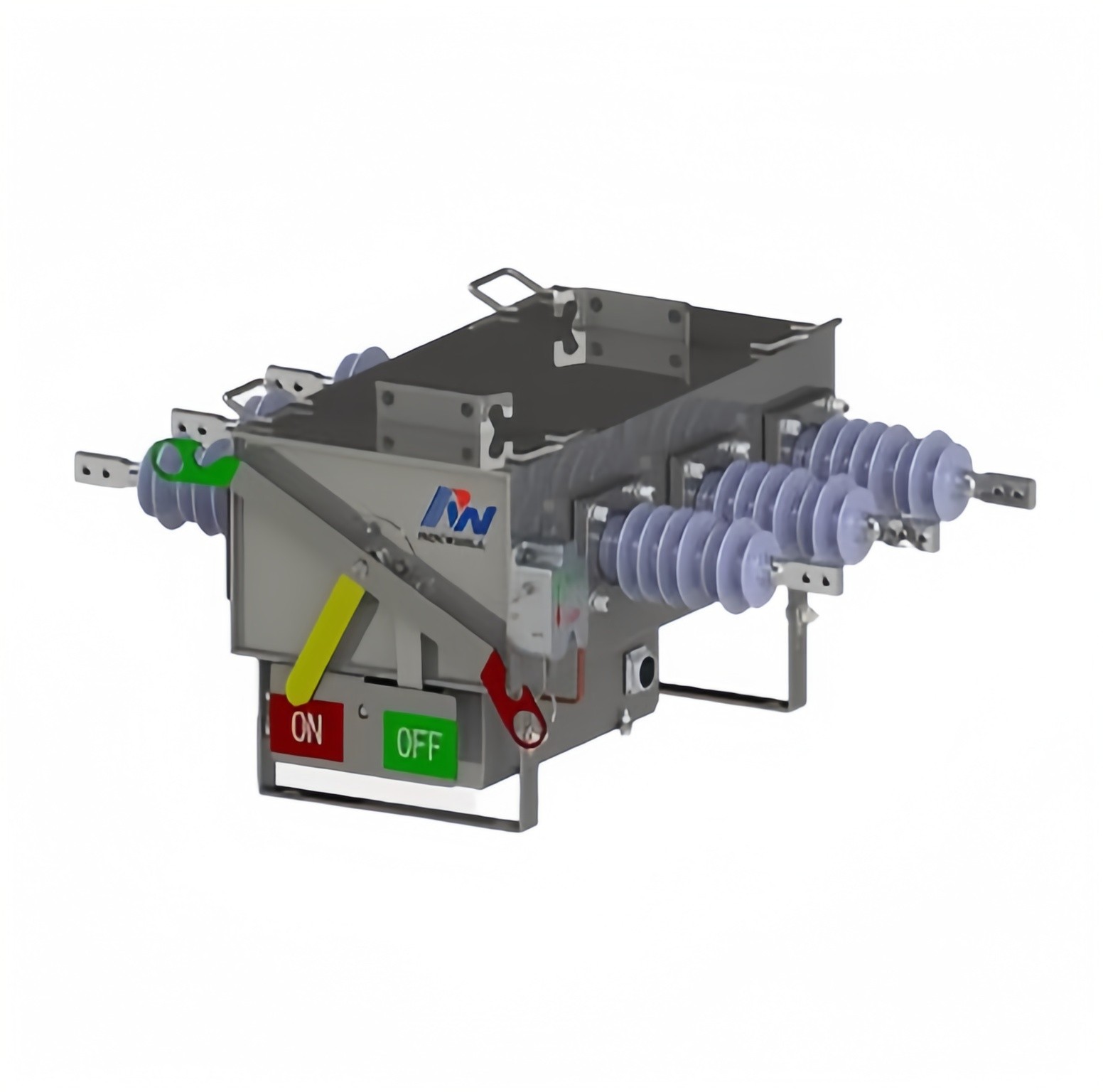
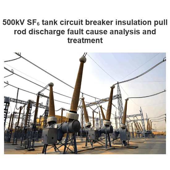
This is a high standard design SF6 gas load break switch which is suit for pole mounted.
RPS type load break switch is KEMA type tested.
RPS type load break switch can combined as below different functions switchgear:
Manual type load break switch
Motorize type load break switch
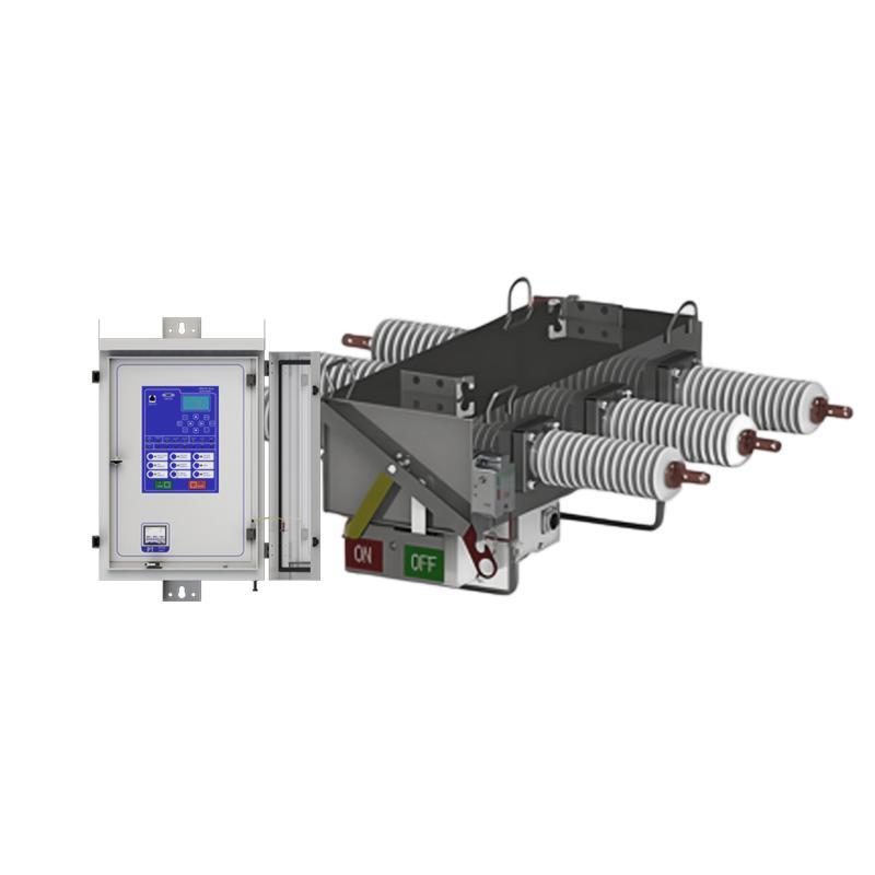
Remote control load break switch
Automatic sectionalizer
Features:
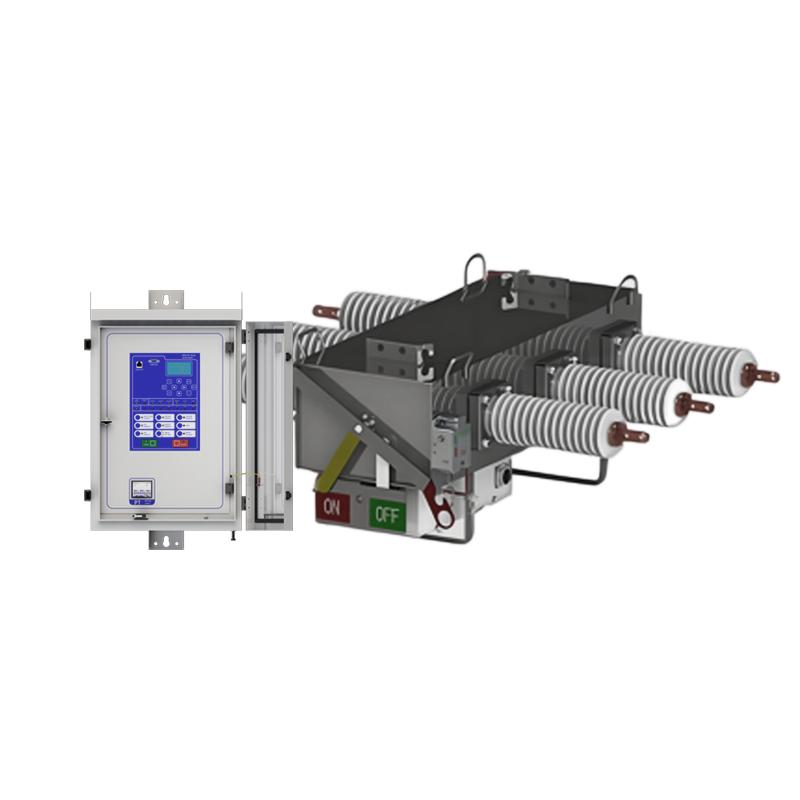
The high quality 3 mm stainless steel are used for tank.
Minimum welding line to minimize corrosion, and specifically to guarantee the safety of the operation personnel.
Even with the internal arc faults at the maximum fault capacity of the tank the RPS can withstands an internal fault without venting hot gases.
The independent spring operation mechanism adopt ROCKWILL® patent spiral spring, provides a guaranteed load break fault make capability by ensuring the opening and closing speed of the switch.
Provided with light reflecting position indicator which are directly connected to the switch operating shaft providing clear and unambiguous switch position indication.
Indicator made of light reflecting material, which is easily visible from ground level even at night in driving rain.
Parameters:
Outdoor RPS-15kV/1250A SF6 load break switch |
|
Rated voltage |
15kV |
Power frequency withstand voltage |
50Hz |
to earth and between phases |
28kV |
across the isolating distance |
32kV |
to earth and between phases |
75kV |
across the isolating distance |
85kV |
Rated normal current |
1250A |
Mainly active load breaking current |
1250A |
Number of breaking operations CO |
400times |
Line-charging breaking current |
50A |
Cable-charging breaking curren |
50A |
Earth fault breaking current |
50A |
under earth fault conditions |
28A |
No-load transformer breaking current |
\ |
Short-time withstand current, Ik |
20 kA/4 s |
Peak withstand current |
50kA |
Short-circuit making current |
50kA |
main switch 50 kA (CL E3) |
5times |
main switch 31.5 kA (CL E3) |
10times |
earthing switch 50 kA (CL E2) |
3times |
earthing switch 31.5 kA (CL E3) |
5times |
Ambient air temperature limits |
-40°C...+60°C |
main switch |
5000times |
earthing switch |
2000times |
Filling pressure (+20°C) |
1.4-1.5bar (abs) |
density switch |
1.2bar (abs) |
density gauge |
1.2bar (abs) |
low gas lock-out mechanism |
1.1bar (abs) |
Composite bushing |
115kg |
Porcelain bushing |
125kg |
Motorize |
Add 20kg |
Degree of protection of the mechanism box |
IP67 |
Monitoring Functions:
Monitoring Functions |
Primary/Secondary Phases and Earth Currents |
Direction |
|
Primary/Secondary Line and Phase Voltages |
|
Apparent Power and Power Factor |
|
Real and Reactive Power |
|
Historical Demand Record |
|
Positive Phase Sequence Voltage & Current |
|
Negative Phase Sequence Voltage & Current |
|
Zero Phase Sequence Voltage |
|
Frequency |
|
Binary Input/Output status |
|
Trip circuit healthy/failure |
|
Time and date |
|
Fault records |
|
Event records |
External dimensions:

Size |
889mmx1148mmx557mm |
Environmental requirement:
service environment(area/altitude/Minimum and maximum temperatures) |
Air temperature: Maximum temperature: +85℃; Minimum temperature:-45℃ |
Humidity: Monthly average humidity 95%; Daily average humidity 90% |
|
Altitude above sea level: Maximum installation altitude: 2500m or more higher. |
|
Ambient air not apparently polluted by corrosive and flammable gas, vapor etc. No frequent violent shake |
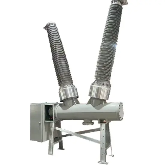
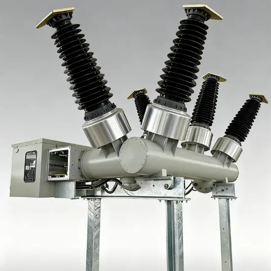
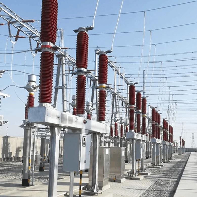
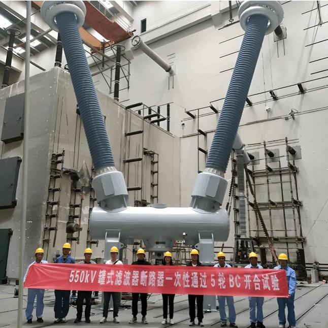
Product show:

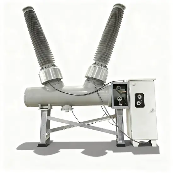
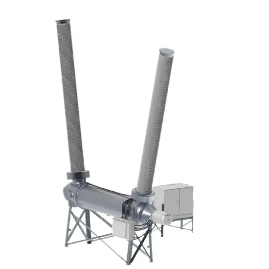
What is a tank circuit breaker compressed air interrupter?
Working Principle:
Working Principle: During the opening operation of the circuit breaker, the moving contact compresses the SF₆ gas within the arc quenching chamber, increasing the gas pressure and causing it to flow rapidly toward the arc region. The high-speed gas flow blows and cools the arc, effectively extinguishing it. During the closing operation, the gas returns to its original state as the moving contact moves in the opposite direction.
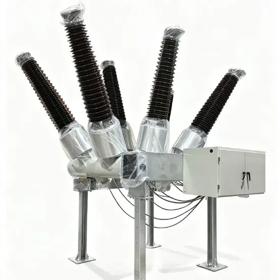
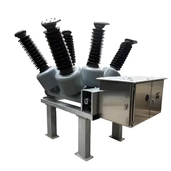
Excellent Interrupting Performance: The pressurized arc quenching chamber offers excellent interrupting performance, with a short arcing time and long electrical life.
Multiple Interruptions: It can continuously interrupt large short-circuit currents at rated voltage multiple times without frequent maintenance.
High Mechanical Reliability: The design ensures high mechanical reliability.
Suitable for High Voltage Systems: It is suitable for transmission and distribution systems operating at 40.5 kV and above. For example, the LW8-40.5 type SF₆ circuit breaker uses a pressurized arc quenching chamber.