Recloser Bypass Switch with Mounting Back Strap
Key attributes
| Brand | ROCKWILL |
| Model NO. | Recloser Bypass Switch with Mounting Back Strap |
| Rated voltage | 38kV |
| Rated normal current | 600A |
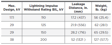
| Rated lightning impulse voltage | 150kV |
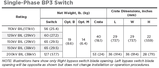
| Series | BP3 |
Product descriptions from the supplier
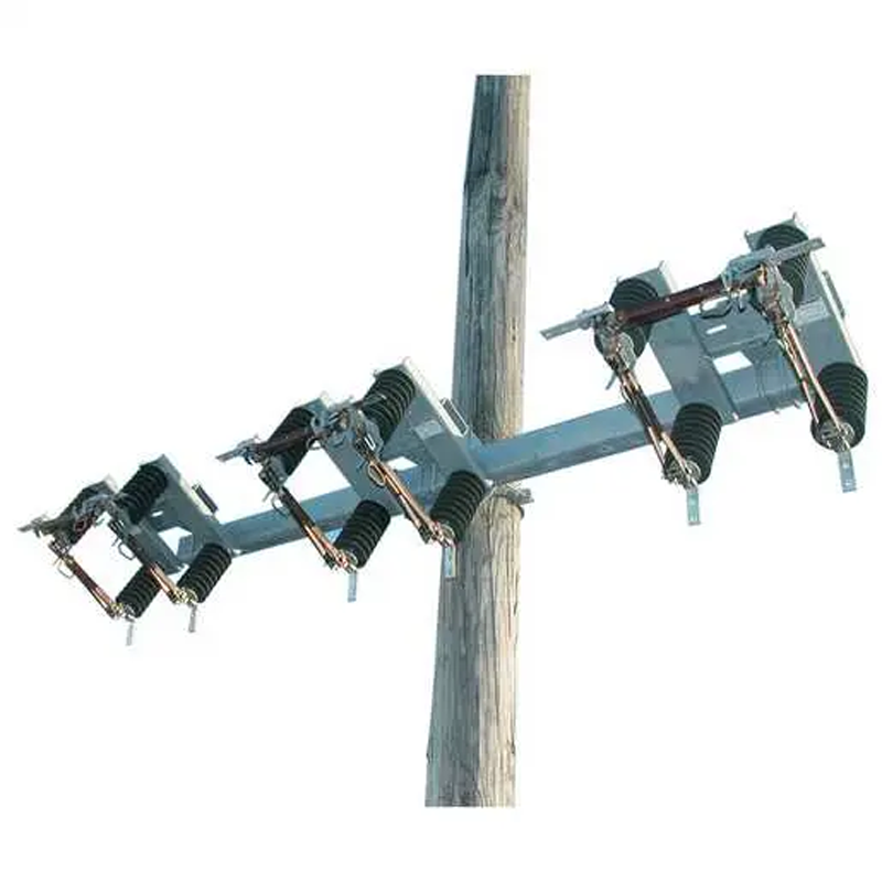
Chance Type BP3 Switches are an economical way to bypass pole mounted distribution reclosers so periodic maintenance can be conducted without interrupting service. The BP3 switches are 3 Pull Operation units that can be offered in either single phase or three phase units. They are rated either 600A or 900A with Voltages Classes of 15, 27 and 38kV with Insulation levels 110kV, 125kV or 150kV BIL. By operating the blades in proper sequence, the recloser is bypassed and isolated from the distribution system. They can be mounted on Cross Arms or directly to the pole via the Pole Mount Bracket Option. They can be configured for either Right Hand or Left Hand opening and either Angled or Non Angled Bypass Blades. Type BP3 switches are not to be used to isolate Voltage Regulators as they have no way to effectively interrupt the circulating current in the regulator windings. Chance: The Brand and Quality You Can Trust!!
Fully Compliant with ANSI/IEEE C37.30.1
15, 27 and 38kV ratings
110, 125 and 150kV BIL ratings
600A and 900A ratings
ESP Polymer 2.25” Bolt Circle Insulator Assemblies
Right Hand and Left Hand opening Options
Non-Angled and Angled Bypass Blade Options
Cross arm or Pole Mount Options
3 Phase on 100” or 124” Cross Arms in Steel or Fiberglass
Principal Application: Recloser Maintenance
By design, the BP3 Switch provides an economical means for bypassing and disconnecting a pole-mounted distribution recloser. This permits de-energized periodic maintenance of the recloser without interrupting service. The BP3 Switch accomplishes this by a combination of three disconnect switches mounted on a common base. By operating the blades in proper sequence, the recloser is bypassed and isolated from the distribution system.
Operation
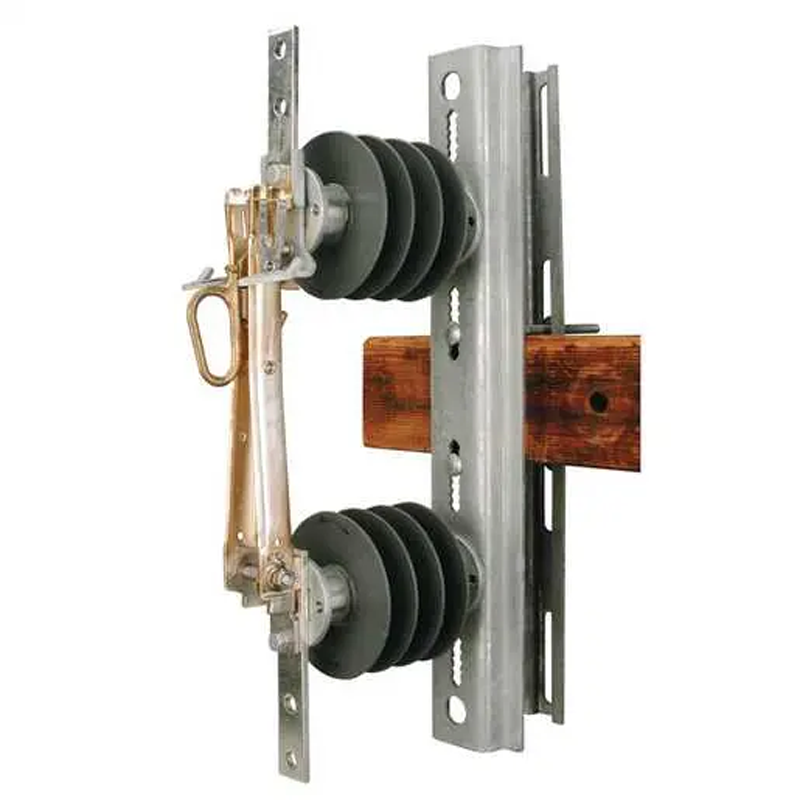
Figures below illustrate the BP3 Bypass Switch operation. In normal operation, the bypass switchblade is open and the two disconnect blades are closed, allowing the recloser to be in the circuit.
When recloser maintenance, testing, repair or removal isrequired, first close the bypass blade to provide a parallel current path. Then open the recloser’s internal contacts. And last, open both disconnect blades of the bypass switch. In this way, service continuity is maintained and the recloser is isolated from the line. To put the recloser back in service, the switch operating procedure is reversed.
Parameters

Related Products


Related Knowledges
-
 Impact of DC Bias in Transformers at Renewable Energy Stations Near UHVDC Grounding ElectrodesImpact of DC Bias in Transformers at Renewable Energy Stations Near UHVDC Grounding ElectrodesWhen the grounding electrode of an Ultra-High-Voltage Direct Current (UHVDC) transmission system is located close to a renewable energy power station, the return current flowing through the earth can cause a rise in ground potential around the electrode area. This ground potential rise leads to a shift in the neutral-point potential of nearby power transformers, inducing DC bias (or DC offset) in their01/15/2026
 -
 HECI GCB for Generators – Fast SF6 Circuit Breaker1.Definition and Function1.1 Role of the Generator Circuit BreakerThe Generator Circuit Breaker (GCB) is a controllable disconnect point located between the generator and the step-up transformer, serving as an interface between the generator and the power grid. Its primary functions include isolating generator-side faults and enabling operational control during generator synchronization and grid connection. The operating principle of a GCB is not significantly different from that of a standard c01/06/2026
 -
 Distribution Equipment Transformer Testing, Inspection, and Maintenance1.Transformer Maintenance and Inspection Open the low-voltage (LV) circuit breaker of the transformer under maintenance, remove the control power fuse, and hang a “Do Not Close” warning sign on the switch handle. Open the high-voltage (HV) circuit breaker of the transformer under maintenance, close the grounding switch, fully discharge the transformer, lock the HV switchgear, and hang a “Do Not Close” warning sign on the switch handle. For dry-type transformer maintenance: first clean the porcel12/25/2025
 -
 How to Test Insulation Resistance of Distribution TransformersIn practical work, insulation resistance of distribution transformers is generally measured twice: the insulation resistance between thehigh-voltage (HV) windingand thelow-voltage (LV) winding plus the transformer tank, and the insulation resistance between theLV windingand theHV winding plus the transformer tank.If both measurements yield acceptable values, it indicates that the insulation among the HV winding, LV winding, and transformer tank is qualified. If either measurement fails, pairwise12/25/2025
 -
 Design Principles for Pole-Mounted Distribution TransformersDesign Principles for Pole-Mounted Distribution Transformers(1) Location and Layout PrinciplesPole-mounted transformer platforms should be located near the load center or close to critical loads, following the principle of “small capacity, multiple locations” to facilitate equipment replacement and maintenance. For residential power supply, three-phase transformers may be installed nearby based on current demand and future growth projections.(2) Capacity Selection for Three-Phase Pole-Mounted Tr12/25/2025
 -
 Transformer Noise Control Solutions for Different Installations1.Noise Mitigation for Ground-Level Independent Transformer RoomsMitigation Strategy:First, conduct a power-off inspection and maintenance of the transformer, including replacing aged insulating oil, checking and tightening all fasteners, and cleaning dust from the unit.Second, reinforce the transformer foundation or install vibration isolation devices—such as rubber pads or spring isolators—selected based on the severity of vibration.Finally, strengthen sound insulation at weak points of the ro12/25/2025
Related Solutions
-
 Intelligent Operation Solution for 12kV Vacuum Circuit Breakers: Integrating Real-time Monitoring & Lifetime OptimizationⅠ. Equipment Operation & MaintenanceIntelligent Monitoring System IntegrationMulti-parameter Real-time Monitoring: Embedded sensors (temperature, displacement, Hall effect current sensors) track contact temperature rise, mechanical characteristics (opening/closing speed, overtravel), coil current, and partial discharge signals. Data undergoes preprocessing via edge computing prior to cloud upload.Lifetime Prediction Model: Dynamically evaluates remaining lifespan using electrical wear data06/10/2025
 -
 SF6 Circuit Breaker Solutions for Outdoor Installation (Anti-Pollution & Seismic Resistance)I.Core Challenges in Outdoor InstallationIn high-voltage transmission and distribution systems, SF6 circuit breakers are exposed to complex outdoor environments for extended periods, facing the following critical issues:Pollution & Insulation DegradationDust, salt fog, and industrial pollutants in outdoor environments easily adhere to equipment surfaces. In coastal or industrial areas, pollution levels may reach Class IV, resulting in insufficient creepage distance and triggering flasho05/12/2025
 -
 12kV Indoor Vacuum Circuit Breaker Southeast Asia Solution: Anti-Corrosion Compact Design12kV Indoor Vacuum Circuit Breaker Southeast Asia Solution: Anti-Corrosion Compact DesignⅠ. Executive SummarySoutheast Asia faces rapidly growing electricity demand alongside environmental challenges including high temperatures, humidity, salt spray corrosion, and grid instability. This solution recommends Solid Insulated Pole-Mounted Vacuum Circuit Breakers (VCB) featuring high reliability, compact design, and smart monitoring. Tailored for tropical climates and industrial scenarios, it06/10/2025


