• Product
  • Suppliers
  • Manufacturers
  • Solutions
  • Free tools
  • Knowledges
  • Experts
  • Communities
Search


Skid mounted substation

  • Skid mounted substation

Key attributes

Brand Wone Store
Model NO. Skid mounted substation
Design code 215
Series SSU

Product descriptions from the supplier

Description

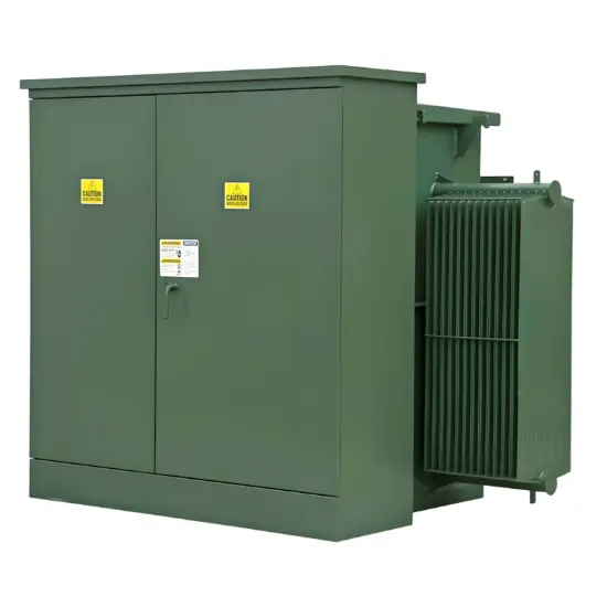
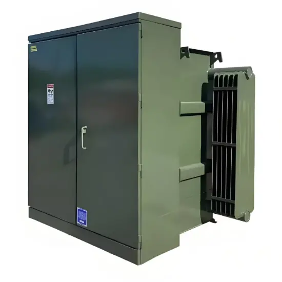
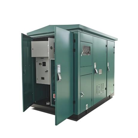
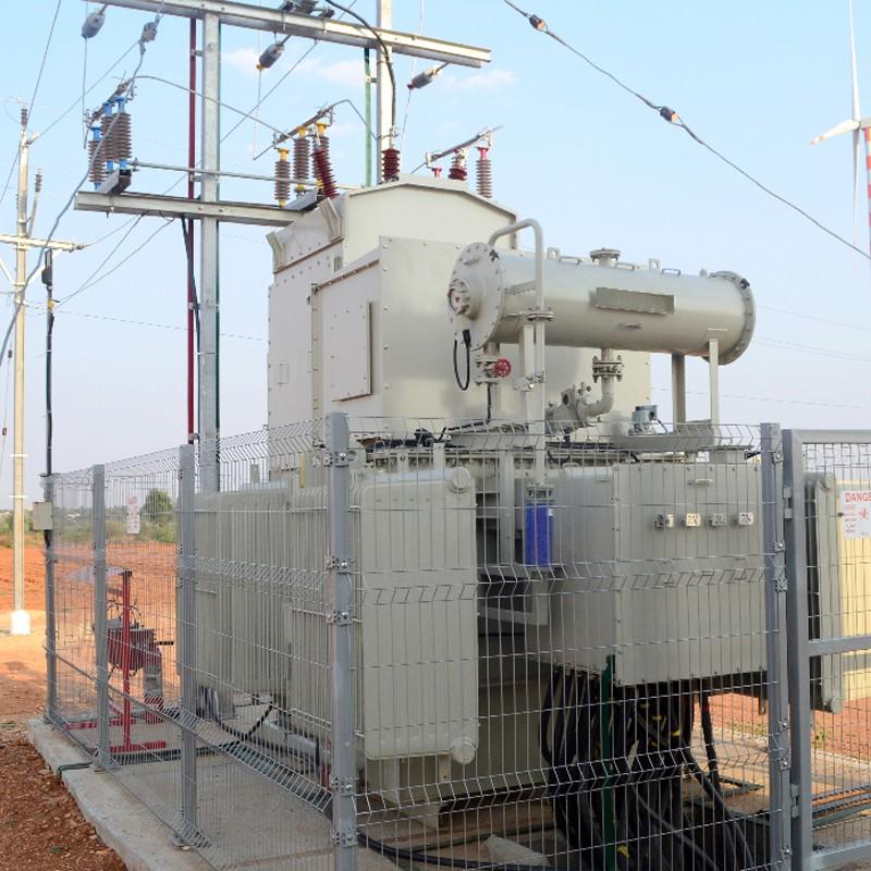
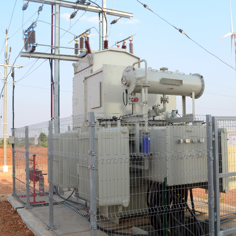
Skid mounted substations developed up to 5 MVA, 0.75 – 40.5 KV(HV) for wind mills which provides transformer integrated with HV side protection gear complete with breaker and panel. The complete unit comprised of transformer, HV bushings to breaker panel bus-duct, HV breaker & panel, LV side cable box connections. All components were designed to be assembled on single skid and transported to customer premises a single unit. The entire assembly was reinforced at critical points to bear transportation loads. The transformer was sent with radiator/conservator mounted and completely oil filled to avoid any mounting and oil filtration at site.

The skid mounted substation resulted in great savings for customer in terms of erection time and the space needed when compared with conventional DP yard substations. The savings in space was estimated to be close to 50% and the erection time crashed by 60%.

Different components

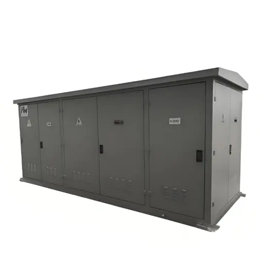
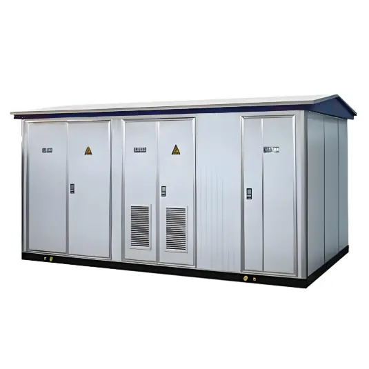
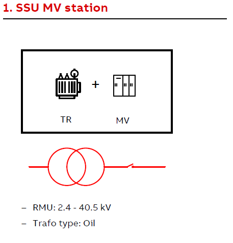
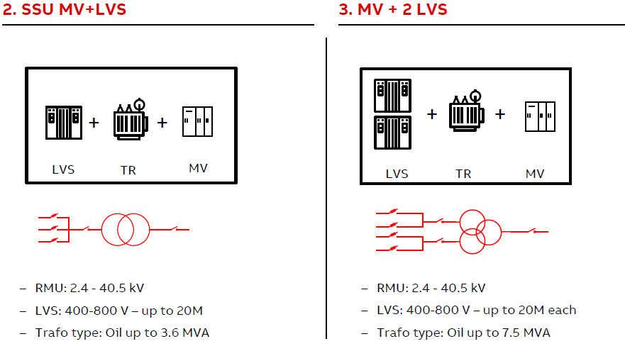
The skid unit generally have these main components:
● MV switchgear -up to 40.5 kV
● Transformer -up to 7.5 MVA, oil-type
● Low voltage switchgear or panels –Up to 1 kV
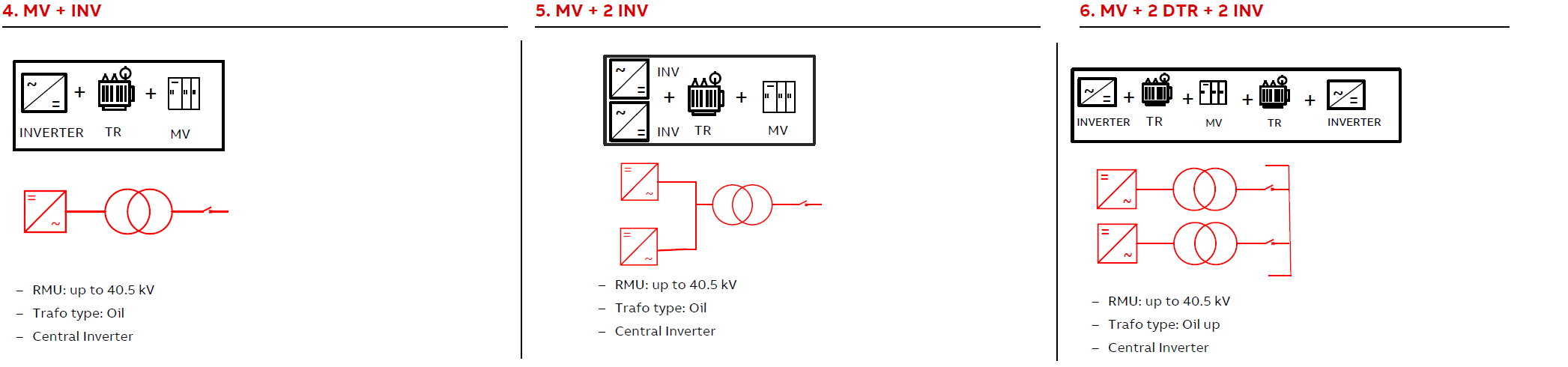
● Others –inverter, bus duct

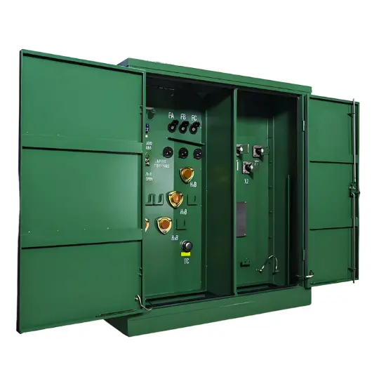
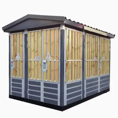
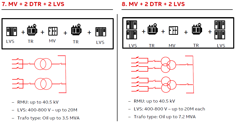
Further reducing the installation work on site while increasing the power of DTR
● One common RMU and auxiliary cabinet
● Twin Transformer
● Twin Central inverter
● or LV cabinet for connection to string inverter

Detail portfolio and product description

Component

Parameters

Value

RMU

Rated   voltage

40.5kV

Rated   current

630A

Transformer

Insulation   type

Oil-type

Rated   capacity

3.6MVA

HV   side voltage

36kV

HV   side voltage

0.4kV

Component

parameters

value

RMU

Rated voltage

40.5kV

Rated current

630A/1250A

Transformer

Insulation   type

Oil-type

Rated capacity

3.6MVA/7.2MVA

HV side voltage

36kV

HV sidevoltage

0.4kV

LV switchgear

Rated voltage

0.4kV

Rated current

4000A

Component

parameters

value

RMU

Rated voltage

40.5kV

Rated current

630A/1250A

Transformer

Insulation   type

Oil-type

Rated capacity

3.6MVA/7.2MVA

HV side voltage

36kV

HV side voltage

0.4kV

Inverter/PCS

Rated AC-Bus voltage

AC 0.4kV

Rated DC-Bus voltage

DC 768V

Rated current

4000A


Component

parameters

value

RMU

Rated voltage

40.5kV

Rated current

630A/1250A

Transformer

Insulation   type

Oil-type

Rated capacity

3.6MVA/7.2MVA

HV side voltage

36kV

HV side voltage

0.4kV

LV switchgear

Rated voltage

0.4kV

Rated current

4000A

Documentation Resource Library
Restricted
The solution for Skid mounted Substation
Operation manual
English
Consulting
Consulting
Know your supplier
Online store
On-time delivery rate
Response time
100.0%
≤4h
Company overview
Workplace: 1000m² Total staff: Highest Annual Export(usD): 300000000
Workplace: 1000m²
Total staff:
Highest Annual Export(usD): 300000000
Services
Business Type: Sales
Main Categories: Wire cable/High Voltage Electrical Apparatus/Low Voltage Electrical Apparatus/Instrument meters/New energy/Tester/Integrated Electrical Equipment/Production equipment/Generator/Electrical fittings/Instrument Transformer/Equipment Parts
Whole life care manager
Whole-life care management services for equipment procurement, use, maintenance, and after-sales, ensuring safe operation of electrical equipment, continuous control, and worry-free electricity consumption.
The equipment supplier has passed platform qualification certification and technical evaluation, ensuring compliance, professionalism, and reliability from the source.

Related Products

Related Knowledges

  • Impact of DC Bias in Transformers at Renewable Energy Stations Near UHVDC Grounding Electrodes
    Impact of DC Bias in Transformers at Renewable Energy Stations Near UHVDC Grounding ElectrodesWhen the grounding electrode of an Ultra-High-Voltage Direct Current (UHVDC) transmission system is located close to a renewable energy power station, the return current flowing through the earth can cause a rise in ground potential around the electrode area. This ground potential rise leads to a shift in the neutral-point potential of nearby power transformers, inducing DC bias (or DC offset) in their
    01/15/2026
  • HECI GCB for Generators – Fast SF6 Circuit Breaker
    1.Definition and Function1.1 Role of the Generator Circuit BreakerThe Generator Circuit Breaker (GCB) is a controllable disconnect point located between the generator and the step-up transformer, serving as an interface between the generator and the power grid. Its primary functions include isolating generator-side faults and enabling operational control during generator synchronization and grid connection. The operating principle of a GCB is not significantly different from that of a standard c
    01/06/2026
  • Distribution Equipment Transformer Testing, Inspection, and Maintenance
    1.Transformer Maintenance and Inspection Open the low-voltage (LV) circuit breaker of the transformer under maintenance, remove the control power fuse, and hang a “Do Not Close” warning sign on the switch handle. Open the high-voltage (HV) circuit breaker of the transformer under maintenance, close the grounding switch, fully discharge the transformer, lock the HV switchgear, and hang a “Do Not Close” warning sign on the switch handle. For dry-type transformer maintenance: first clean the porcel
    12/25/2025
  • How to Test Insulation Resistance of Distribution Transformers
    In practical work, insulation resistance of distribution transformers is generally measured twice: the insulation resistance between thehigh-voltage (HV) windingand thelow-voltage (LV) winding plus the transformer tank, and the insulation resistance between theLV windingand theHV winding plus the transformer tank.If both measurements yield acceptable values, it indicates that the insulation among the HV winding, LV winding, and transformer tank is qualified. If either measurement fails, pairwise
    12/25/2025
  • Design Principles for Pole-Mounted Distribution Transformers
    Design Principles for Pole-Mounted Distribution Transformers(1) Location and Layout PrinciplesPole-mounted transformer platforms should be located near the load center or close to critical loads, following the principle of “small capacity, multiple locations” to facilitate equipment replacement and maintenance. For residential power supply, three-phase transformers may be installed nearby based on current demand and future growth projections.(2) Capacity Selection for Three-Phase Pole-Mounted Tr
    12/25/2025
  • Transformer Noise Control Solutions for Different Installations
    1.Noise Mitigation for Ground-Level Independent Transformer RoomsMitigation Strategy:First, conduct a power-off inspection and maintenance of the transformer, including replacing aged insulating oil, checking and tightening all fasteners, and cleaning dust from the unit.Second, reinforce the transformer foundation or install vibration isolation devices—such as rubber pads or spring isolators—selected based on the severity of vibration.Finally, strengthen sound insulation at weak points of the ro
    12/25/2025

Related Solutions

  • Dedicated Vacuum Contactor Solution for Port Shore Power Systems
    I. Background and Challenges​Shore power systems have become core technical equipment for ports to reduce carbon emissions and noise pollution. However, these systems face two major challenges in the harsh operational environment of ports:​Severe Environmental Corrosion: High humidity and salt spray in port areas cause serious corrosion to metal components and enclosures of electrical equipment, significantly impacting electrical lifespan and operational reliability.​High Switching Requirements:
    09/13/2025
  • ABB Vacuum Contactor KC2 Power Supply System Technical Transformation Plan
    Issue Overview​The 10kV air compressor starting system of a company utilizes the ABB vacuum contactor KC2 as the control component for the operating circuit. The dedicated wide-voltage power supply module paired with this contactor presents the following issues:​Frequent failures: The power supply module fails to properly transition the voltage from 300V to 12V, resulting in fuse blowouts.​Poor heat dissipation: Enclosed installation of the module leads to insufficient heat dissipation, acceler
    09/13/2025
  • Solution for Medium-Voltage Motor Control and Protection Using Vacuum Contactor-Fuse (VCF) in a Coal Conveying System
    1.Project BackgroundA coal conveying system comprises 15 belt conveyors driven by medium-voltage motors. The system operates under complex conditions, with motors often subjected to heavy loads and frequent starts. To address these challenges and achieve effective control and reliable protection during motor startup, the project comprehensively adopts Vacuum Contactor-Fuse (VCF) combination devices for the 6kV medium-voltage motor power distribution. This solution details the technical features,
    09/13/2025
Haven't found the right supplier yet? Let matching verified suppliers find you. Get Quotation Now
Haven't found the right supplier yet? Let matching verified suppliers find you.
Get Quotation Now
Send inquiry
Download
Get the IEE Business Application
Use the IEE-Business app to find equipment, obtain solutions, connect with experts, and participate in industry collaboration anytime, anywhere—fully supporting the development of your power projects and business.