Solar Power Equipment Box-type Transformer(Prefabricated Substation)

Key attributes
| Brand | Vziman |
| Model NO. | Solar Power Equipment Box-type Transformer |
| Rated voltage | 33kV |
| Capacity | 500kVA-1600kVA |
| Series | Compact Substation |
Product descriptions from the supplier
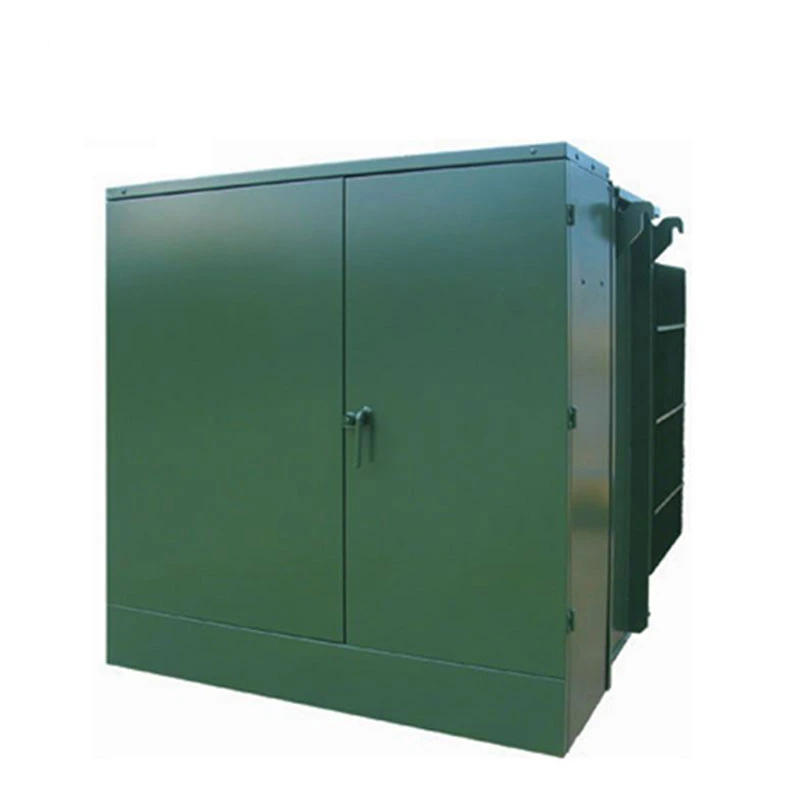
Product overview:
A Solar Power Equipment Box-type Transformer that integrates 0.27kV 0.315kV 0.69kv voltage of grid-connected photovoltaic inverter into power grid output energy through a boost transformer.
High-voltage switchgear, transformer body and protective fuse are centrally placed in the oil tank. High-voltage/low-voltage pre-installed substation is set up together with low-voltage switchgear and corresponding auxiliary equipment.
Mainly used for small and medium-sized solar power generation.
Execution standard: IEC61850 series, GB/T17467, etc.
Product advantages:
Leading technology:
Standard anti-corrosion and salt spray environmental plan to meet the stringent environmental requirements of the site.
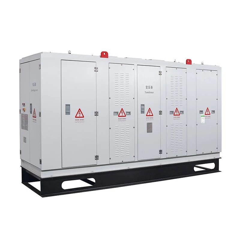
Compact structure, small footprint, easy installation.
Fully enclosed, fully insulated structure, safe and reliable operation.
Easy to operate, maintenance-free, low equipment cost.
Enclosure:
Adopt cold rolled high quality hot dip galvanized sheet.
The surface is treated by electrostatic spray, and the paint can not be taken off for 50 years.
Laser numerical control equipment cutting, drilling, bending, to ensure the processing accuracy.
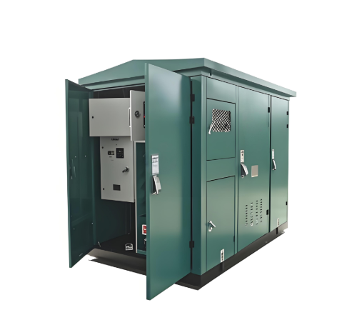
Product structure is divided into three parts: high voltage chamber, low voltage chamber and transformer.
The cabinet is mainly pre-installed with: lightning arrester, load switch, transformer tap switch, protection fuse, oil level thermometer, oil level gauge, pressure relief valve, amount of oil discharge valve and other accessories.
The low-voltage side is equipped with main circuit breaker, overvoltage protector, and can be designed and installed in complete sets of automatic measurement and intelligent control system.
The transformer is a low loss oil-immersed transformer produced by WONE You Electric.
Functional units:
Fully sealed structure, using the transformer insulating oil as the insulating medium and heat dissipation medium, overall has the advantages of compact structure, good heat dissipation performance.
The high-voltage indoor door should be equipped with electromagnetic lock and live display. When the high-voltage side is live, the high-voltage chamber door cannot be opened.
The external door of the box transformer should be equipped with mechanical lock to meet the five requirements of high-pressure products and ensure personal safety.
Components:
Choose high-quality brand components such as Chint, Shanghai People Electric, Changshu Electric, etc.
Schneider, ABB high-quality partners.
Supplementary material:
High quality tin - plated busbar copper bar, with insulation sleeve.
Hanhe cable is selected for secondary wiring.
Processing and assembly:
Assembly workers have been trained for at least 6 months.
Secondary wiring is fully automatic equipment cutting to ensure reliable wiring.
Use power tools to ensure proper torque for bolting reinforcement.
The copper wire bus is NC punched and bent.
All kinds of experimental tests before leaving the factory to ensure normal operation.
Product parameters:
Voltage:0.69kV/33kV 0.69kV/11kV.
Conditions of use:
Altitude: ≦2000m.
Ambient temperature range: -45℃ -- +45℃.
Outdoor wind speed: ≤35m/s.
Relative humidity: daily mean ≤95%, monthly mean ≤90%.
Installation location: Install in the place without fire, explosion risk, serious pollution, chemical corrosion and violent vibration.
If the above normal operating conditions are exceeded, customers can contact our company for customized solutions.
The above is suitable for 50/60Hz photovoltaic power generation system, the rated capacity of the transformer is 500~ 1600kVA.
Ordering instructions:
When ordering, the customer shall provide the following information:
Main loop scheme diagram and secondary loop system diagram.
Electrical schematic diagram of auxiliary circuit and wiring terminal layout.
Equipment layout drawing, combination drawing, floor plan drawing.
Brand, model, specification and quantity of main electrical components of the equipment.
Incoming and outgoing line method and cable specifications.
Device surface color.
Other special requirements can be negotiated with the manufacturer.

Related Products
-
YBS-Smart Transformer Station

-
33kV unitized compact substation

-
12kV 24kV 36kV 40.5kV Prefabricated Substation(US-style, EU-style)

-
11kV 20kV 35KV Pad Mounted Transformer(Prefabricated Substation)
-
Wind Power Equipment Box-type Transformer(Prefabricated Substation)

-
Compact and Prefabricated Substation
-
Shield chassis type substation Prefabricated Substation
Related Knowledges
-
 Impact of DC Bias in Transformers at Renewable Energy Stations Near UHVDC Grounding ElectrodesImpact of DC Bias in Transformers at Renewable Energy Stations Near UHVDC Grounding ElectrodesWhen the grounding electrode of an Ultra-High-Voltage Direct Current (UHVDC) transmission system is located close to a renewable energy power station, the return current flowing through the earth can cause a rise in ground potential around the electrode area. This ground potential rise leads to a shift in the neutral-point potential of nearby power transformers, inducing DC bias (or DC offset) in their01/15/2026
 -
 HECI GCB for Generators – Fast SF6 Circuit Breaker1.Definition and Function1.1 Role of the Generator Circuit BreakerThe Generator Circuit Breaker (GCB) is a controllable disconnect point located between the generator and the step-up transformer, serving as an interface between the generator and the power grid. Its primary functions include isolating generator-side faults and enabling operational control during generator synchronization and grid connection. The operating principle of a GCB is not significantly different from that of a standard c01/06/2026
 -
 Distribution Equipment Transformer Testing, Inspection, and Maintenance1.Transformer Maintenance and Inspection Open the low-voltage (LV) circuit breaker of the transformer under maintenance, remove the control power fuse, and hang a “Do Not Close” warning sign on the switch handle. Open the high-voltage (HV) circuit breaker of the transformer under maintenance, close the grounding switch, fully discharge the transformer, lock the HV switchgear, and hang a “Do Not Close” warning sign on the switch handle. For dry-type transformer maintenance: first clean the porcel12/25/2025
 -
 How to Test Insulation Resistance of Distribution TransformersIn practical work, insulation resistance of distribution transformers is generally measured twice: the insulation resistance between thehigh-voltage (HV) windingand thelow-voltage (LV) winding plus the transformer tank, and the insulation resistance between theLV windingand theHV winding plus the transformer tank.If both measurements yield acceptable values, it indicates that the insulation among the HV winding, LV winding, and transformer tank is qualified. If either measurement fails, pairwise12/25/2025
 -
 Design Principles for Pole-Mounted Distribution TransformersDesign Principles for Pole-Mounted Distribution Transformers(1) Location and Layout PrinciplesPole-mounted transformer platforms should be located near the load center or close to critical loads, following the principle of “small capacity, multiple locations” to facilitate equipment replacement and maintenance. For residential power supply, three-phase transformers may be installed nearby based on current demand and future growth projections.(2) Capacity Selection for Three-Phase Pole-Mounted Tr12/25/2025
 -
 Transformer Noise Control Solutions for Different Installations1.Noise Mitigation for Ground-Level Independent Transformer RoomsMitigation Strategy:First, conduct a power-off inspection and maintenance of the transformer, including replacing aged insulating oil, checking and tightening all fasteners, and cleaning dust from the unit.Second, reinforce the transformer foundation or install vibration isolation devices—such as rubber pads or spring isolators—selected based on the severity of vibration.Finally, strengthen sound insulation at weak points of the ro12/25/2025
Related Solutions
-
 Choosing Vizman Distribution Transformers: Innovative Customization to Meet Diverse Power NeedsDistribution transformers are the heart of local electricity distribution systems. They step down voltage, enabling safe and efficient power supply to homes and businesses.At Vizman Electric Power Technology Co., Ltd., we understand the critical role of distribution transformers in the energy ecosystem. That's why we specialize in manufacturing high-quality distribution transformers, providing tailored solutions to meet diverse energy needs.1.Solutions Offered by Vizman Electric Power Technology04/16/2025
 -
 SF6 Circuit Breaker Solutions in High-Voltage Power Systems: A Case Study of VZIMAN Company1. Challenges in High-Voltage Power Systems1.1 High-voltage power systems, as the core of power transmission, face critical challenges:Equipment Performance Limits: With increasing voltage levels (e.g., 500kV and above), traditional circuit breakers struggle to meet high breaking capacities (over 40kA) and rapid insulation recovery requirements.Overvoltage Risks: Switching capacitive loads (e.g., capacitor banks) may cause reignition, leading to dangerous overvoltages.Poor Environmental Ada05/13/2025
 -
 VZIMAN Company SF6 Circuit Breaker Solutions for Renewable Energy Grid Integration1. Current Challenges in Renewable Energy Grid Integration1.1 Grid Frequency Fluctuations and Stability IssuesThe intermittency and variability of renewable energy sources (e.g., wind and solar) lead to frequent grid frequency changes. Traditional circuit breakers struggle to respond rapidly to such dynamic loads, potentially causing equipment damage or regional blackouts. For instance, during sudden drops in wind power or abrupt solar output fluctuations, the grid must isolate faults within m05/13/2025


