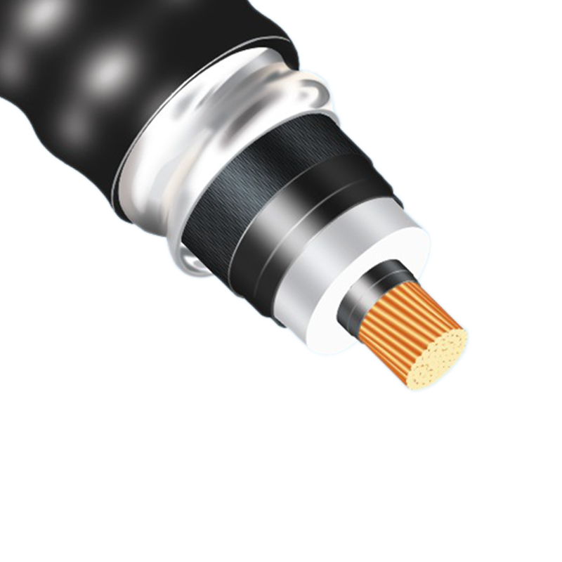
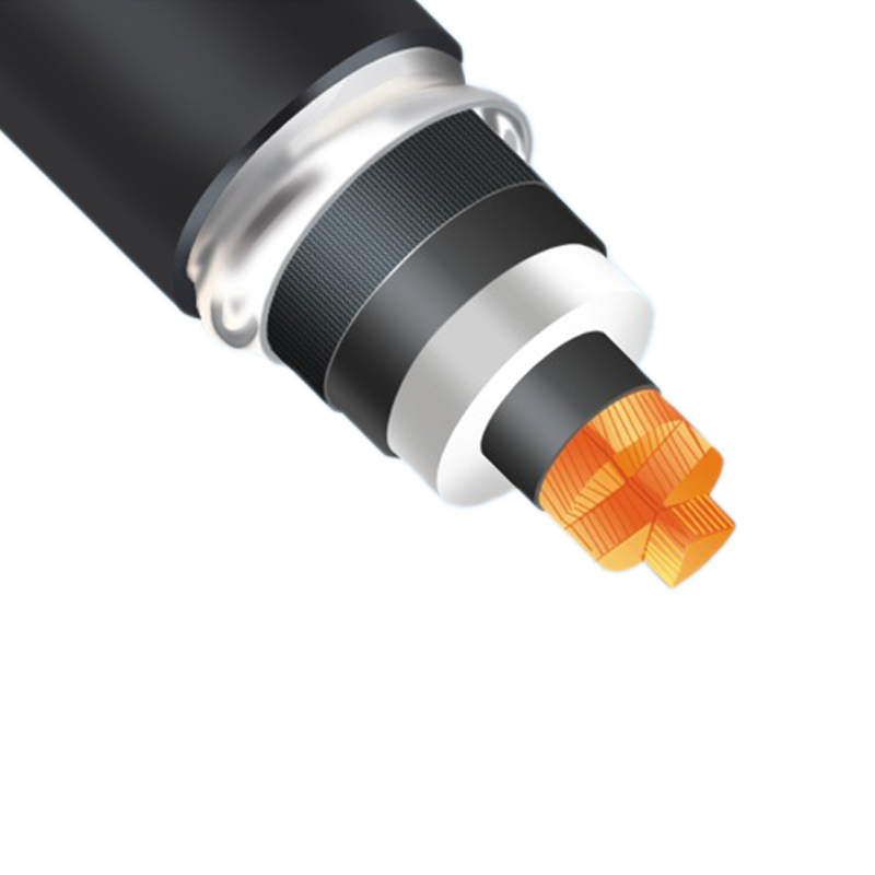
YJLW Series cross-linked cable
discuss personally
Model
YJLW03-Z-500/1x800
YJLW02-Z-500/1x800
YJLW03-500/1x800
YJLW02-500/1x800
YJLW03-Z-220/1x800
YJLW02-Z-220/1x800
YJLW03-220/1x800
YJLW02-220/1x800
YJLLW03-Z-132/1x800
YJLLW02-Z-132/1x800
YJLLW03-132/1x800
YJLLW02-132/1x800
YJLW03-Z-132/1x800
YJLW02-Z-132/1x800
YJLW03-132/1x800
YJLW02-132/1x800
YJLLW03-Z-110/1x800
YJLLW02--Z110/1x800
YJLLW03-110/1x800
YJLLW02-110/1x800
YJLW03-Z-110/1x800
YJLW02-Z-110/1x800
YJLW03-110/1x800
YJLW02-110/1x800
YJLLW03-Z-66/1x800
YJLLW02-Z-66/1x800
YJLLW03-66/1x800
YJLLW02-66/1x800
YJLW03-Z-66/1x800
YJLW02-Z-66/1x800
YJLW03-66/1x800
YJLW02-66/1x800
YJLW03-Z-220/1x630
YJLW02-Z-220/1x630
YJLW03-220/1x630
YJLW02-220/1x630
YJLLW03-Z-132/1x630
YJLLW02-Z-132/1x630
YJLLW03-132/1x630
YJLLW02-132/1x630
YJLW03-Z-132/1x630
YJLW02-Z-132/1x630
YJLW03-132/1x630
YJLW02-132/1x630
YJLLW03-Z-110/1x630
YJLLW02-Z-110/1x630
YJLLW03-110/1x630
YJLLW02-110/1x630
YJLW03-Z-110/1x630
YJLW02-Z-110/1x630
YJLW03-110/1x630
YJLW02-110/1x630
YJLLW03-Z-66/1x630
YJLLW02-Z-66/1x630
YJLLW03-66/1x630
YJLLW02-66/1x630
YJLW03-Z-66/1x630
YJLW02-Z-66/1x630
YJLW03-66/1x630
YJLW02-66/1x630
YJLW03-Z-220/1x500
YJLW02-Z-220/1x500
YJLW03-220/1x500
YJLW02-220/1x500
YJLLW03-Z-132/1x500
YJLLW02-Z-132/1x500
YJLLW03-132/1x500
YJLLW02-132/1x500
YJLW03-Z-132/1x500
YJLW02-Z-132/1x500
YJLW03-132/1x500
YJLW02-132/1x500
YJLLW03-Z-110/1x500
YJLLW02-Z-110/1x500
YJLLW03-110/1x500
YJLLW02-110/1x500
YJLW03-Z-110/1x500
YJLW02-Z-110/1x500
YJLW03-110/1x500
YJLW02-110/1x500
YJLLW03-Z-66/1x500
YJLLW02-Z-66/1x500
YJLLW03-66/1x500
YJLLW02-66/1x500
YJLW03-Z-66/1x500
YJLW02-Z-66/1x500
YJLW03-66/1x500
YJLW02-66/1x500
YJLW03-Z-220/1x400
YJLW02-Z-220/1x400
YJLW03-220/1x400
YJLW02-220/1x400
YJLLW03-Z-132/1x400
YJLLW02-Z-132/1x400
YJLLW03-132/1x400
YJLLW02-132/1x400
YJLW03-Z-132/1x400
YJLW02-Z-132/1x400
YJLW03-132/1x400
YJLW02-132/1x400
YJLLW03-Z-110/1x400
YJLLW02-Z-110/1x400
YJLLW03-110/1x400
YJLLW02-110/1x400
YJLW03-Z-110/1x400
YJLW02-Z-110/1x400
YJLW03-110/1x400
YJLW02-110/1x400
YJLLW03-Z-66/1x400
YJLLW02-Z-66/1x400
YJLLW03-66/1x400
YJLLW02-66/1x400
YJLW03-Z-66/1x400
YJLW02-Z-66/1x400
YJLW03-66/1x400
YJLW02-66/1x400
YJLLW03-Z-132/1x300
YJLLW02-Z-132/1x300
YJLLW03-132/1x300
YJLLW02-132/1x300
YJLW03-Z-132/1x300
YJLW02-Z-132/1x300
YJLW03-132/1x300
YJLW02-132/1x300
YJLLW03-Z-110/1x300
YJLLW02-Z-110/1x300
YJLLW03-110/1x300
YJLLW02-110/1x300
YJLW03-Z-110/1x300
YJLW02-Z-110/1x300
YJLW03-110/1x300
YJLW02-110/1x300
YJLLW03-Z-66/1x300
YJLLW02-Z-66/1x300
YJLLW03-66/1x300
YJLLW02-66/1x300
YJLW03-Z-66/1x300
YJLW02-Z-66/1x300
YJLW03-66/1x300
YJLW02-66/1x300
YJLLW03-Z-132/1x240
YJLLW02-Z-132/1x240
YJLLW03-132/1x240
YJLLW02-132/1x240
YJLW03-Z-132/1x240
YJLW02-Z-132/1x240
YJLW03-132/1x240
YJLW02-132/1x240
YJLLW03-Z-110/1x240
YJLLW02-Z-110/1x240
YJLLW03-110/1x240
YJLLW02-110/1x240
YJLW03-Z-110/1x240
YJLW02-Z-110/1x240
YJLW03-110/1x240
YJLW02-110/1x240
YJLLW03-Z-66/1x240
YJLLW02-Z-66/1x240
YJLLW03-66/1x240
YJLLW02-66/1x240
YJLW03-Z-66/1x240
YJLW02-Z-66/1x240
YJLW03-66/1x240
YJLW02-66/1x240