• 550kV HV Gas Insulated Switchgear (GIS)
550kV HV Gas Insulated Switchgear (GIS)
discuss personally
Model
ZF27-550/6300-63
Basic info
Brand ROCKWILL
Model NO. 550KV GIS Gas Insulated Switchgear (GIS)
Rated voltage 550kV
Rated normal current 6300A
Series ZF27
Product Detail

Description:


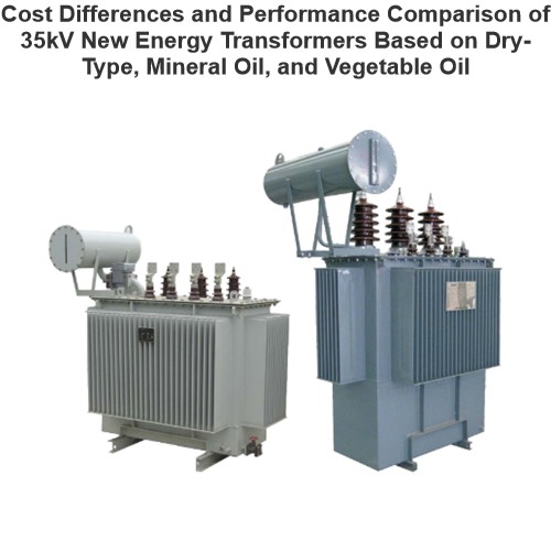
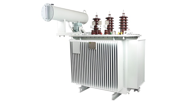
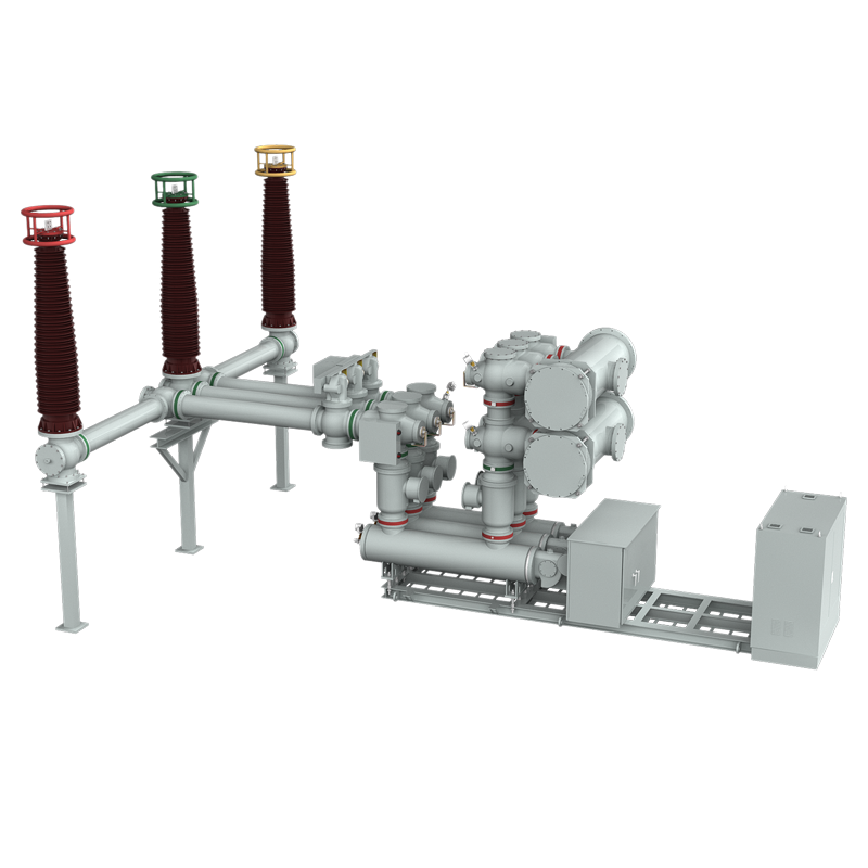
The ZF27 - 550, an independently developed 550KV - level Gas Insulated Switchgear (GIS), boasts technical parameters at the international leading edge. Tailored for 550KV power systems, it enables seamless control, measurement, and protection. Comprising key components like circuit breakers, disconnectors, earthing switches, quick earthing switches, current transformers, busbars, and air - insulated bushings for power inlets and outlets, other components are enclosed in an earthed shell with SF6 gas serving as both arc - extinguishing and insulating medium. It can be flexibly configured into various connection modes per user needs.


Main Features:


  • The circuit breaker features a single - fracture arcing chamber with a simple, rational structure and advanced technology.

  • It offers robust breaking capabilities, an extended electrical contact lifespan, and a long service life.

  • The circuit breaker unit can be installed on - site without opening the chamber and filled with SF6 gas directly, preventing dust and foreign matter ingress.

  • The innovative hydraulic operating mechanism has minimal external piping, reducing the likelihood of oil leakage.

  • During operation, the hydraulic operating mechanism is automatically regulated by the pressure switch, maintaining a constant rated oil pressure regardless of ambient temperature. Its relief valve safeguards against overpressure risks.

  • In case of pressure loss, the hydraulic operating mechanism prevents slow tripping during pressure restoration.

  • The closing resistance of the product can be optionally installed or removed based on user requirements.

Technical Parameters:

1718679970148.png

What are the technical parameters of gas-insulated Switchgear?

Rated Voltage:

  • Common rated voltage levels include 72.5kV, 126kV, 252kV, 363kV, and 550kV. The rated voltage determines the maximum operating voltage that the equipment can withstand and is a crucial factor in the design and selection of GIS (Gas-Insulated Switchgear) equipment. It must match the voltage level of the power system to ensure that the equipment operates safely and reliably under both normal and fault conditions.

Rated Current:

  • The rated current ranges from a few hundred amperes to several thousand amperes, such as 1250A, 2000A, 3150A, 4000A, etc. The rated current indicates the maximum current that the equipment can carry continuously without damage. When selecting the equipment, it is necessary to consider a certain margin based on the actual load conditions to ensure that the equipment does not fail due to overload during normal operation and can also meet future load growth requirements.

Rated Short-Circuit Breaking Capacity:

  • Typically, the rated short-circuit breaking capacity ranges from 31.5kA to 63kA or even higher. This parameter measures the equipment's ability to interrupt short-circuit currents. When a short-circuit fault occurs in the power system, the short-circuit current increases dramatically. The GIS equipment must be able to quickly and reliably interrupt the short-circuit current to prevent the fault from escalating. The rated short-circuit breaking capacity must be greater than the maximum possible short-circuit current in the system to ensure the safety performance of the equipment during a short-circuit condition.

SF₆ Gas Pressure:

  • The rated pressure of SF₆ gas in the equipment is generally between 0.3MPa and 0.7MPa. The actual operating pressure may be adjusted according to the specific requirements of the equipment and environmental factors such as temperature. During operation, it is necessary to monitor and control parameters such as the pressure, humidity, and purity of the SF₆ gas to ensure they remain within specified limits. This ensures the insulation and arc-quenching performance of the equipment.


Know your supplier
ROCKWILL
Rockwill Electric Group Global Manufacturer of High voltage and medium-voltage power equipment and smart grid solutions. Headquartered in Wenzhou, China. Serving 100+ countries with quality, innovation, and trust. What We Offer: • HV-MV switchgear (VCB, SF₆ circuit breakers, RMU, GIS) • Distribution transformers and substations • Smart grid and monitoring systems • Solar, wind, EV charging, and energy storage solutions • EPC turnkey power projects Certified: ISO 9001 / ISO 14001 / ISO 45001
Main Categories
High Voltage Electrical Apparatus
Business Type
Design/Manufacture/Sales
Highest Annual Export (USD)
$150,000,000
Professional Experience
16 years
Workplace
108000m²m²
占位
占位
Related Products
Related Knowledges
Cost Differences and Performance Comparison of 35kV New Energy Transformers Based on Dry-Type, Mineral Oil, and Vegetable Oil
For users, when purchasing a 35kV new energy transformer, choosing between dry-type, mineral oil-filled, or vegetable oil-filled types involves multiple considerations. These include user habits, maintenance-free performance, safety and fire resistance, volume and weight, among others. However, cost differences are undoubtedly one of the most crucial factors.To illustrate the issue intuitively, this paper selects a three-level energy efficiency dual-winding new energy transformer with a rated ca
Ron
07/26/2025
What is the connection group of a transformer?
Transformer Connection GroupThe connection group of a transformer refers to the phase difference between the primary and secondary voltages or currents. It is determined by the winding directions of the primary and secondary coils, the labeling of their start and end terminals, and the connection mode. Expressed in a clock-like format, there are 12 groups in total, numbered from 0 to 11.The DC method is commonly used to measure the transformer's connection group, mainly to verify whether the con
Vziman
07/26/2025
Working Voltage in Power System
Working VoltageThe term "working voltage" refers to the maximum voltage that a device can withstand without sustaining damage or burning out, while ensuring the reliability, safety, and proper operation of both the device and associated circuits.For long-distance power transmission, the use of high voltage is advantageous. In AC systems, maintaining a load power factor as close to unity as possible is also economically necessary. Practically, heavy currents are more challenging to handle than hi
Encyclopedia
07/26/2025
What is Steady State Stability in Power System?
Definition of Steady State StabilitySteady state stability is defined as the capability of an electric power system to sustain its initial operating condition following a small disturbance, or to converge to a state closely approximating the initial condition when the disturbance persists. This concept holds critical significance in power system planning and design, the development of specialized automatic control devices, the commissioning of new system components, and the adjustment of operati
Edwiin
07/26/2025
What is the sequence for powering down the transformer?
The sequence for shutting down a main transformer is as follows: when de-energizing, the load side should be shut down first, followed by the power supply side. For energizing operations, the reverse order applies: the power supply side is energized first, then the load side. This is because: Energizing from the power supply side to the load side makes it easier to identify the fault range and take prompt judgment and handling measures in case of a fault, preventing the fault from spreading or e
Rockwell
07/26/2025
What are the methods for switching operations of station transformers?
Let's take an auxiliary power system with two station transformers as an example. When one station transformer needs to be out of service, there are two operation methods: non-interruptive power supply and instantaneous power interruption. Generally, the method of instantaneous power interruption on the low-voltage side is preferred.The operation method for instantaneous power interruption on the low-voltage side is as follows:Open the 380V power incoming circuit breaker of the corresponding sec
Vziman
07/26/2025
×
Inquiry
Download
IEE-Business is dedicated to serving the personnel in the global power industry.
Join IEE-Business, not only can you discover power equipment and power knowledge, but also canhnd like - minded friends!