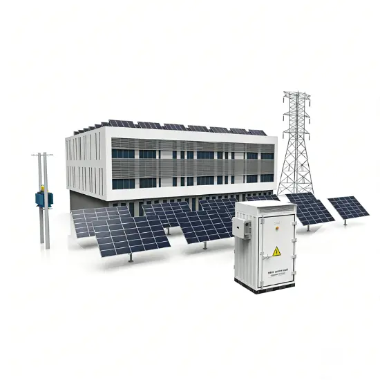
Ⅰ. Problem Scenario
High-frequency harmonic injection from PV plant inverter clusters
During operation of large-scale centralized PV power plants, multiple inverters operating in parallel generate wide-band harmonics in the 150-2500Hz range (primarily the 23rd to 49th harmonics), leading to the following grid-side issues:
Current Total Harmonic Distortion (THDi) reaching 12.3%, significantly exceeding IEEE 519-2014 standard limits.
Causing capacitor bank overload, overheating, and protective device maloperation.
Increased Electromagnetic Interference (EMI) affecting nearby sensitive equipment.
II. Core Solution
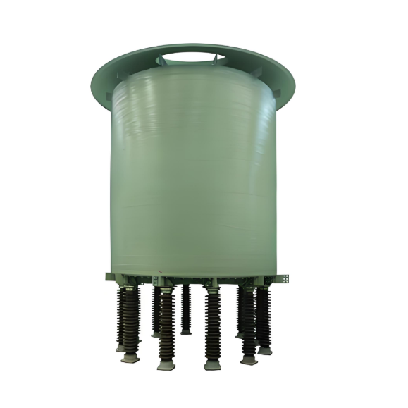
Adoption of an LC passive filter topology, constructing efficient harmonic absorption circuits using customized reactors + capacitor banks.
Key Equipment Selection
Equipment Type |
Model/Specification |
Core Function |
Dry-Type Iron-Core Series Reactor |
CKSC Type (Custom Design) |
Provides precise inductive reactance, suppressing high-frequency harmonics. |
Filter Capacitor Bank |
BSMJ Type (Matched Selection) |
Resonates with reactors to absorb specific harmonic bands. |
Technical Parameter Design
Reactor Inductance: 0.5mH ±5% (@50Hz fundamental frequency)
Quality Factor (Q): >50 (Ensures low-loss high-frequency filtering)
Insulation Class: Class H (Long-term withstand temperature 180°C)
Reactance Ratio Configuration: 5.5% (Optimized for 23rd-49th high-frequency band)
Topology Structure: Delta (Δ) Connection (Enhances high-order harmonic shunting capability)
Filter System Design Key Points
Resonant Frequency Calculation:
f_res = 1/(2π√(L·C)) = 2110Hz
Accurately covers the target frequency band (150-2500Hz), achieving local absorption of high-frequency harmonics.
III. EMC Mitigation Effectiveness Validation
Indicator |
Before Mitigation |
After Mitigation |
Standard Limit |
THDi |
12.3% |
3.8% |
≤5% (IEEE 519) |
Individual Harmonic Distortion |
Up to 8.2% |
≤1.5% |
Compliant with GB/T 14549 |
Capacitor Temperature Rise |
75K |
45K |
Compliant with IEC 60831 |
IV. Engineering Implementation Advantages
High-Efficiency Filtering:
The 5.5% reactance ratio design specifically suppresses harmonics above the 23rd order, providing a 40% improvement in high-frequency response compared to traditional 7% schemes.
Safety and Reliability:
The Class H temperature rise insulation system ensures stable equipment operation in outdoor environments ranging from -40°C to +65°C.
Cost Optimization:
The low-loss design (Q > 50) results in additional system power consumption of < 0.3% of output power.
V. Deployment Recommendations
Installation Location: Low-voltage side busbar of the 35kV collection substation.
Configuration: Each 2Mvar capacitor bank series-connected with 10 CKSC reactors (Group-based automatic switching).
Monitoring Requirement: Install an online harmonic analyzer to track THDi changes in real-time.
Solution Value: Effectively resolves high-frequency harmonic pollution in new energy power stations, extends capacitor lifespan by over 37%, and avoids PV output curtailment due to harmonic violation penalties.